34 Rockwell Automation Publication 2080-UM002L-EN-E - November 2021
Chapter 2 About Your Controller
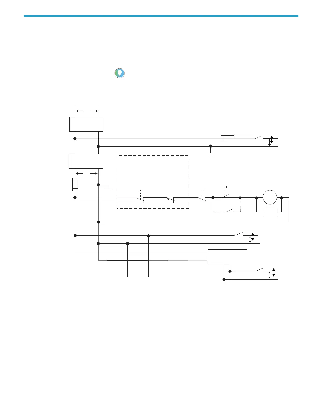
• In the following illustration, input and output circuits are shown with
MCR protection. However, in most applications, only output circuits
require M
CR protection.
The following illustrations show the Master Control Relay wired in a grounded
system.
Figure 1 - Schematic – Using IEC Symbols
In most applications input circuits do not require MCR protection; however, if
you need to remove power from all field devices, you must include MCR
contacts in series with input power wiring.
Disconnect
Isolation
transformer
Emergency-stop
push button
Fuse
MCR
230V AC
I/O circuits
Operation of either of these contacts will remove
power from the external I/O circuits, stopping
machine motion.
Fuse
Overtravel limit
switch
MCR
MCR
MCR
Stop Start
Line terminals: Connect to terminals of power supply.
115V AC or 230V AC
I/O circuits
L1
L2
230V AC
Master Control Relay (MCR)
Cat. No. 700-PK400A1
Suppressor
Cat. No. 700-N24
MCR
Suppr.
24V DC
I/O circuits
(Lo)
(Hi)
DC power supply.
Use IEC 950/EN 60950
X1 X2
115V AC
or 230V AC
Line terminals: Connect to 24V DC terminals of power supply.
_
+

 Loading...


