52 Rockwell Automation Publication 20B-IN017B-EN-P - September 2011
Chapter 3 Component Replacement Procedures
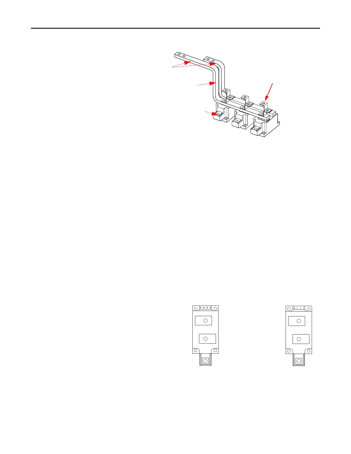
12. Remove the Converter Bus Bars (DC+ and DC–).
13. Disconnect the SCR gate leads.
14. Remove the four (4) Phillips screws that hold each SCR to the Heatsink.
15. Remove the SCR modules.
Install Components
1. Using isopropyl alcohol, thoroughly clean the surface of the Heatsink.
2. Verify that the mounting surface of each new SCR module is clean. If
not, clean with isopropyl alcohol.
3. Using a 3" putty knife or similar tool, apply a thin even coating of the
supplied thermal grease to the mounting surface of each SCR module.
Use enough thermal grease to create a conductive coating, but not so
much that the two surfaces can rock.
Important: In the next step, take care to not disturb any of the thermal grease on
the SCR module.
4. Install each new SCR module with supplied screws and tighten using
this torque sequence:
SCR module
Converter
Bus Bars
DC+
DC–
DC Choke
Connectors
Snubber Board
Mounting Bracket
➊➌
➍➋
SCR Torque
First Sequence:
0.7 N-m (6.0 lb.-in.)
SCR Torque
Final Sequence:
5.6 N-m (50 lb.-in.)
➌
➍➋
➊

 Loading...


