Rockwell Automation Publication 20B-IN017B-EN-P - September 2011 53
Component Replacement Procedures Chapter 3
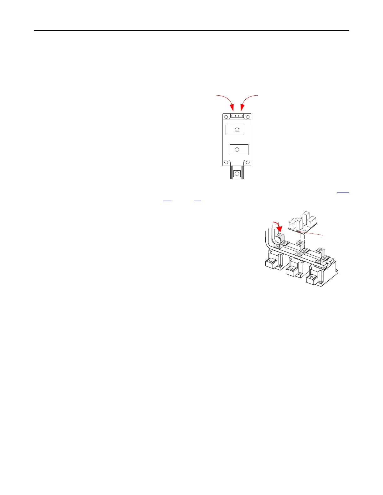
5. Install the SCR module leads from the Precharge Board J2 and J3. For
each SCR module, the left connection is for the J3 lead and the right
connection is for the J2 lead.
Note: J3 has its red wire on the left and white wire on the right, while J2
has its red wire on the right and white wire on the left.
6. Install the Converter Bus Bars (DC+ and DC–) per the diagram in Step
12. on page 52 but do not torque screws at this time.
7. Install the Snubber Board
Mounting Brackets oriented as
in the diagram to the right,
Torque to 9.0 N•m (80 lb•in)
8. Install Snubber Boards, oriented
with the serial number as shown
in the diagram to the right.
Torque to 2.9 N•m (26 lb•in)
9. Replace leads.
10. Install AC Bus Bars (R, S, T). Torque both ends to 9.0 N•m (80 lb•in)
11. Torque screws for Converter Bus Bars to 9.0 N•m (80 lb•in)
12. Reassemble remaining components in reverse order.
13. Replace all safety shields and enclosure covers before applying power to
the drive.
J3 Lead
Connection
J2 Lead
Connection
Serial
Number
Label
Snubber Board
Mounting Bracket

 Loading...


