Rockwell Automation Publication 20D-PM001D-EN-P - March 2019 41
Programming and Parameters Chapter 2
148 FW TaskTime Actl
Displays the actual firmware scan times selected by Par 146 [FW TaskTime Sel]. Before the change to the firmware
scan time is accepted, the drive evaluates the change to ensure the processor will not be overloaded. If there is risk
of overloading the processor, the change will not be accepted.
Default:
Options:
0 =
0 =
1 =
2 =
3 =
4 =
5 =
6 =
7 =
8 =
“0.5 /2 /8ms”
“0.5 /2 /8ms”
“0.5 /1 /8ms”
“0.25 /1 /8ms”
“0.25 /0.5 /8ms”
“0.1/0.5 /8ms”
“0.5/1 /2ms”
“0.25 /1 /2ms”
“0.25 /0.5 /2ms”
“0.1/0.5 /2ms”
RO 16-bit
Integer
149 FW FunctionsActl
Displays the actual state of the firmware functions. If activating requested functions could overload the processor, the change to Par 147 [FW Functions En] will not be accepted.
Note: Bit 19 “MotinPlanner” and 24 “PhaseLockLp” were added for firmware version 3.001
150 Logic State Mach
Indicates the logical state of the drive.
• “Stopped” indicates zero speed has been detected and the speed and torque regulators are disabled.
• 8 “Slip Test” indicates that the Slip Frequency Auto Tune test is in progress.
• 11 “Sleep Mode” indicates that the drive has entered sleep mode.
Note: Value 11 “Sleep Mode” was added for firmware version 5.002. Value 8 “Slip Test” was added for firmware
version 3.001. Values 9 “Finding Home” and 10 “Homing Done” were added for firmware version 3.003.
Default:
Options:
0 =
0 =
1 =
2 =
3 =
4 =
5 =
“Stopped”
“Stopped” 6 = “Test Done”
“Starting” 7 = “EnableHealth”
“Running” 8 = “Slip Test”
“Stopping” 9 = “Finding Home”
“Inertia Test” 10 = “Homing Done”
“MC Diag” 11 = “Sleep Mode”
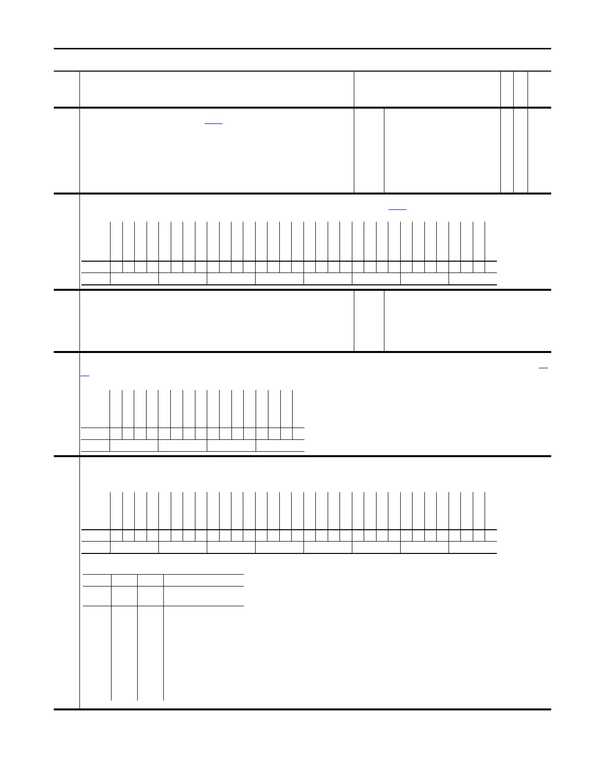
151 Logic Command
The controller-drive interface (as defined by the Controller Communication Format) sets bits to enable and disable various functions and algorithms. Bits that are changed here are reflected in Par
152 [Applied LogicCmd].
Note: Bits 4 through 9 are NOT recalled from Control EEprom. They will be cleared upon drive powerup or following an EEprom recall operation.
152 Applied LogicCmd
Displays the Logic Command that is applied to the Regulators and Control Algorithms within the drive. Logic Commands come from the 32-bit Logic Command found in a connection with the Logix
Controller.
Note: Bits 7 & 8 were changed to “Reserved” for firmware version 2.004.
No. Name
Description
Values
Linkable
Read-Write
Data Type
Options
DvlpmntDeBug
Tren di ng
Reserved
Peak Detect
Test Points
Reserved
Reserved
Phase LockLp
Sync Gener
PosWtch/Dtct
Posit Offset
Posit Motion
MotinPlanner
Posit Pt2Pt
Posit Direct
Posit Interp
DI BitSwaps
Digital Outs
Analog Outs
Analog Ins
Reserved
Reserved
Reserved
Lim/Func Gen
Process Trim
Reserved
Speed Reg
Virt Encoder
FrictionComp
Inertia Comp
Spd Ref Ctrl
Spd Ref Sel
Default 00x00xx0000000000000xxx00x000000
Bit 313029282726252423222120191817161514131211109876543210
0 = False
1 = True
Options
PI Trim Rst
PI Trim Hold
Position En
PI Trim En
Frict Comp
Inertia Comp
Ext Flt/Alm
Reserved
Reserved
SReg IntgRst
SReg IntgHld
SpdRamp Hold
Time Axis En
TachLoss Rst
Spd S Crv En
SpdRamp Dsbl
Default 0000000xx0000000
Bit 1514131211109876543210
0 = False
1 = True
Options
Reserved
Spd Ref Sel2
Spd Ref Sel1
Spd Ref Sel0
Reserved
Reserved
Coast Stop
CurrLim Stop
Jog 2
Reserved
Reverse
Forward
Clear Fault
Jog 1
Start
Normal Stop
PI Trim Rst
PI Trim Hold
Position En
PI Trim En
Frict Comp
Inertia Comp
Ext Flt/Alm
Reserved
Reserved
SReg IntgRst
SReg IntgHld
SpdRamp Hold
Time Axis En
TachLoss Rst
Spd S Crv En
SpdRamp Dsbl
Default x000xx000x0000000000000xx0000000
Bit 313029282726252423222120191817161514131211109876543210
0 = False
1 = True
Speed Reference Select Inputs
Bit 30 Bit 29 Bit 28
Spd Ref
Sel2
Spd Ref
Sel1
Spd Ref
Sel0
Auto Reference Source
0 0 0 Speed Ref A Sel To access Preset Speed 1, set
parameter 27 [Speed Ref A Sel]
or 28 [Speed Ref B Sel] to 5 -
“Preset Spd 1.”
001Speed Ref B Sel
0 1 0 Preset Speed 2
0 1 1 Preset Speed 3
1 0 0 Preset Speed 4
1 0 1 Preset Speed 5
1 1 0 Preset Speed 6
1 1 1 Preset Speed 7
 Loading...


