40 Rockwell Automation Publication 20D-PM001D-EN-P - March 2019
Chapter 2 Programming and Parameters
132 Inert Adapt Sel
Configures the Inertia Adaptation Algorithm (IAA Function).
• Bit 0 “Inrtia Adapt” when set to 1 (on), the Inertia Adaptation function will effect enhanced stability, higher bandwidths and dynamic stiffness. Useful when systems with a gear-box becomes
disconnected from the load. Also used with motors that have very little inertia that otherwise lack dynamic stiffness, even at high bandwidths.
• Bit 1 “Load Est” when set to 1 (on), the Load Estimate option removes or greatly reduces load disturbances and gives quicker system response.
• Bit 2 “First Diff” selects the first difference feedback for Inertia Adaptation.
Notes: When setting both Bit 0 & 1, stability is enhanced and load disturbances are removed. Bit 2 “First Diff” was added for firmware version 3.001.
133 Inert Adapt BW
This parameter sets the bandwidth of the Inertia Adaptation function when the IAA function is selected
(Par
132 [Inert Adapt Sel], bit 0 = 1). Typical IAA bandwidths range from 70 to 150 rad/sec with 100 rad/sec
nominal best.
If the Load Estimate function is selected (Par
132 [Inert Adapt Sel], bit 0 = 1), then this parameter sets the natural
frequency of a filter in rad/sec. Typical values range from 10 to 150 rad/sec with higher values being more
responsive to disturbances but with increased system noise. There is no nominal best value, but 40 rad/sec is a
suggested starting point. This adjustment may not function well in 'sloppy' geared systems.
If both Inertia Adaptation and Load Estimate functions are active, use a bandwidth setting of 100 rad/sec.
Default:
Min/Max:
Units:
100.0000
10.0000/250.0000
rad/s
Y
RW Real
134 Inert Adapt Gain
This parameter sets a multiplier of system inertia when the Inertia Adaptation function is selected
(Par 132 [Inert Adapt Sel], bit 0 = 1). Higher values may cause high frequency ringing, while smaller values may
cause fundamental load instability. A typical value is 0.5 This parameter has no affect on the Load Estimate
function.
Default:
Min/Max:
0.500
0.300/1.000
Y
RW Real
136
137
138
Skip Speed 1
Skip Speed 2
Skip Speed 3
Sets a frequency at which the drive will not operate. [Skip Speed 1 - 3] and Par 139 [Skip Speed Band] must not
equal 0.
Note: These parameters were added for firmware version 2.003.
Default:
Min/Max:
Units:
0.0
–/+30000.0
rpm
Y
RW 16-bit
Integer
139 Skip Speed Band
Determines the bandwidth around a skip frequency. [Skip Speed Band] is split, applying 1/2 above and 1/2 below
the actual skip frequency. The same bandwidth applies to all skip frequencies.
Note: This parameter was added for firmware version 2.003.
Default:
Min/Max:
Units:
0.0
0.0/1000.0
rpm
Y
RW 16-bit
Integer
145 Hardware Present
Indicates if optional hardware is installed.
146 FW TaskTime Sel
Sets the scan times for the drive firmware. Changing the firmware scan times will affect drive performance. Faster
scan times may allow for higher bandwidth of the internal regulators. To achieve faster scan times some functions
may need to be disabled. Only the most demanding application may benefit from faster scan times. Typically,
adjusting this parameter is not needed, it is recommended you consult the factory before changing.
Default:
Options:
0 =
0 =
1 =
2 =
“0.5 /2 /8ms”
“0.5 /2 /8ms”
“0.5 /1 /8ms”
“0.25 /1 /8ms”
RW 16-bit
Integer
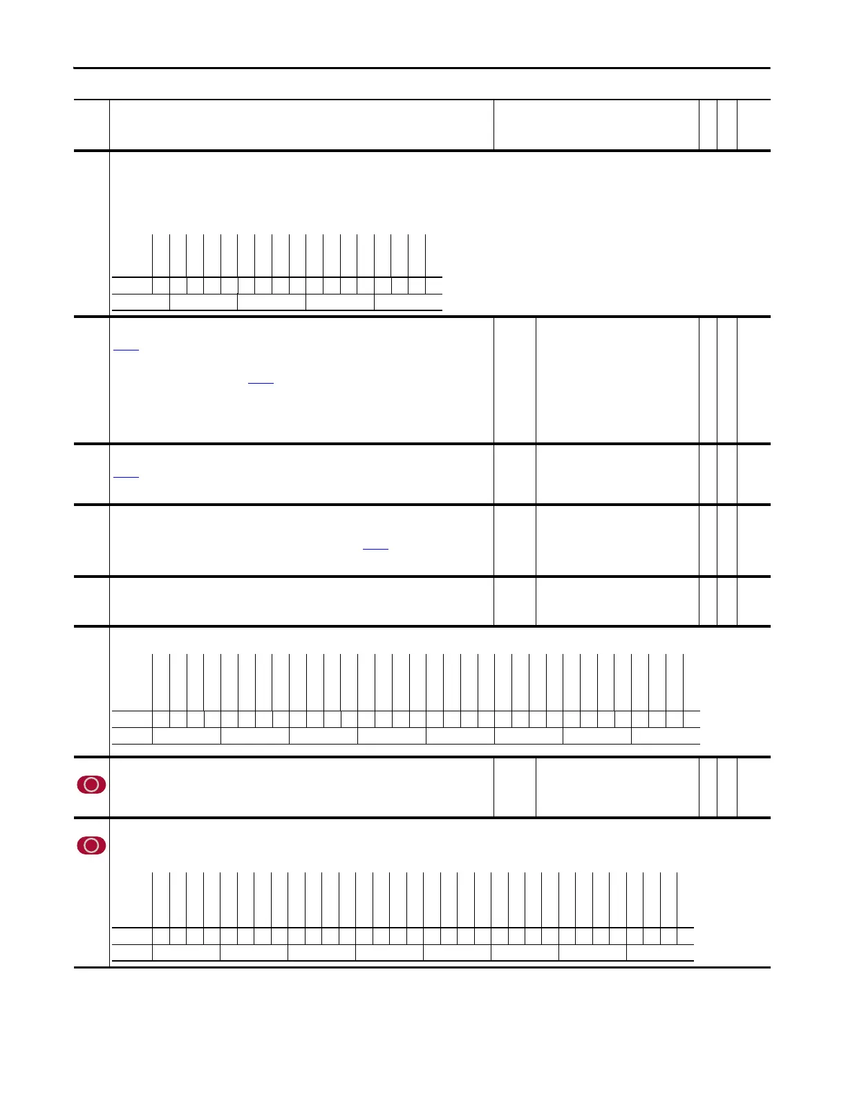
147 FW Functions En
Allows specific firmware functions to be disabled. When a bit is false, the associated function is disabled and all related parameters will be hidden. When a bit is true, the associated function is
enabled and all related parameters will be displayed.
Notes: Bits 18, 20, & 21 were changed to “Reserved” for firmware version 2.004. Bit 19 “MotinPlanner” and 24 “PhaseLockLp” were added for firmware version 3.001.
No. Name
Description
Values
Linkable
Read-Write
Data Type
Options
Reserved
Reserved
Reserved
Reserved
Reserved
Reserved
Reserved
Reserved
Reserved
Reserved
Reserved
Reserved
Reserved
Reserved
First Diff
Load Est
Inrtia Adapt
Default xxxxxxxxxxxxxx000
Bit 161514131211109 8 7 6 5 4 3 2 1 0
0 = False
1 = True
Options
Reserved
Reserved
Reserved
Reserved
Reserved
Reserved
Reserved
Reserved
Reserved
Reserved
Reserved
Reserved
Reserved
Reserved
Reserved
DriveLogix
Stahl Fdbck
Reserved
TemposonFdbk
Resolver Brd
MDI Brd
Heidenhain
StegmannHiRs
2nd Encoder
Reserved
Reserved
SafeOff Brd
Reserved
SynchLinkBrd
Reserved
EmbeddedENET
DPI Comm Brd
Default xxxxxxxxxxxxxxx00x000000xx0x0x00
Bit 313029282726252423222120191817161514131211109876543210
0 = False
1 = True
Options
DvlpmntDeBug
Tren di ng
Reserved
Peak Detect
Test Points
Reserved
Reserved
Phase LockLp
Sync Gener
PosWtch/Dtct
Reserved
Reserved
MotinPlanner
Reserved
Reserved
PositionCtrl
DI BitSwaps
Digital Outs
Analog Outs
Analog Ins
PF700S
Reserved
Reserved
Lim/Func Gen
Process Trim
Reserved
Speed Reg
Virt Encoder
FrictionComp
Inertia Comp
Spd Ref Ctrl
Spd Ref Sel
Default 11x11xx011xx0xx011111xx11x111111
Bit 313029282726252423222120191817161514131211109876543210
0 = False
1 = True
 Loading...


