Rockwell Automation Publication 20D-PM001D-EN-P - March 2019 39
Programming and Parameters Chapter 2
No. Name
Description
Values
Linkable
Read-Write
Data Type
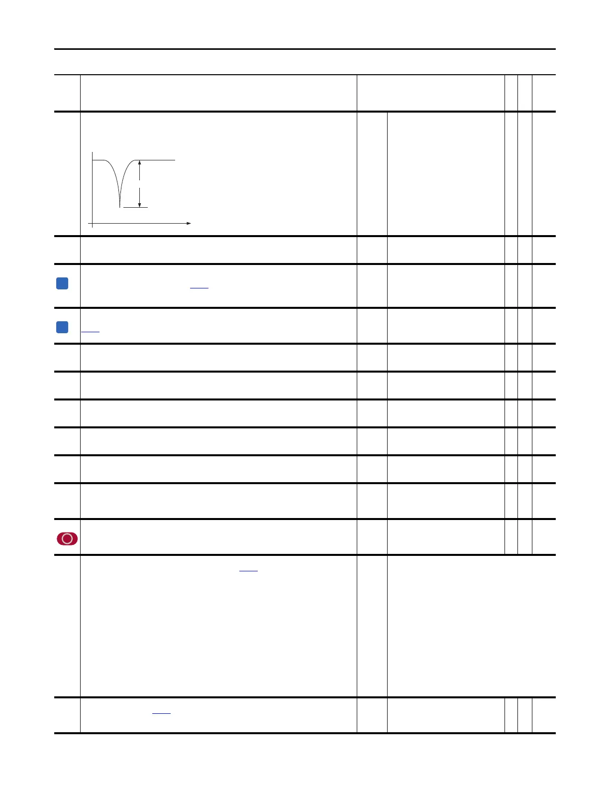
117 NotchAttenuation
Sets the depth for the Notch Filter. Attenuation is the ratio of the output to the input at the notch frequency. An
attenuation of 30 means that the notch output is 1/30
th
of the input at the specified frequency.
Calculation: Attenuation = Input / Output
Default:
Min/Max:
50
0/500
Y
RW Real
118 Notch Filt Freq
The center frequency for Notch filter. To disable, set to zero (0).
Default:
Min/Max:
Units:
0.0000
0.0000/500.0000
Hz
Y
RW Real
119 SLAT ErrorSetpnt
Determines the rpms at which the drive will switch from speed mode to the Speed Limited Adjustable Torque
(SLAT) min. or SLAT max. mode, identified in Par
110 [Speed/Torque Mode] bit 7 “SLAT Minimum” or bit 8 “SLAT
Maximum”.
Note: This parameter was added for firmware version 3.001.
Default:
Min/Max:
Units:
0.005
0.0/0.1
rpm
Y
RW Real
120 SLAT Dwell Time
SLAT control dwell time. The time in seconds that the drive can be above the error set point in
Par 119 [SLAT ErrorSetpnt] before returning to the SLAT min. or SLAT max. mode.
Note: This parameter was added for firmware version 3.001.
Default:
Min/Max:
Units:
0.0
0.0/2.0
s
Y
RW Real
123 Trq PosLim Actl
Sets the internal torque limit for positive torque reference values. The positive internal motor torque will not be
allowed to exceed this value.
Default:
Min/Max:
Units:
1.0
0.0/8.0
P. U .
RO Real
124 Trq NegLim Actl
Sets the internal torque limit for negative torque reference values. The internal negative motor torque will not be
allowed to exceed this value.
Default:
Min/Max:
Units:
-1.0
-8.0/0.0
P. U .
RO Real
125 Torque Pos Limit
Sets the external torque limit for positive torque reference values. The external positive motor torque will not be
allowed to exceed this value.
Default:
Min/Max:
Units:
2.0000
0.0000/8.0000
P. U .
Y
RW Real
126 Torque Neg Limit
Sets the external torque limit for negative torque reference values. The external negative motor torque will not be
allowed to exceed this value.
Default:
Min/Max:
Units:
-2.0000
-8.0000/0.0000
P. U .
Y
RW Real
127 Mtring Power Lim
Sets the maximum motoring (positive) power of the drive. This can be calculated by multiplying the desired
maximum motor torque and the maximum motor speed. A value of 1.0 = nominal motor power.
Default:
Min/Max:
Units:
8.0000
0.0000/8.0000
P. U .
Y
RW Real
128 Regen Power Lim
Sets the maximum regenerative (negative) power of the drive. This can be calculated by multiplying the desired
maximum motor torque and the maximum motor speed. A value of 1.0 = nominal motor power.
Note: The default value for this parameter was changed from -1.0000 to -0.5000 for firmware version 2.003.
Default:
Min/Max:
Units:
-0.5000
-8.0000/0.0000
P. U .
Y
RW Real
129 Atune Trq Ref
Sets the motor torque that is applied to the motor during the flux current and inertia tests.
Note: The minimum value for this parameter was changed from 0.2500 to 0.2000 for firmware version 2.003.
Default:
Min/Max:
Units:
Scale:
0.50
0.2/1.0
P. U .
1.0 = P.U. Motor to Torque
RW Real
130 Trq Ref TP Sel
Enter or write a value to select torque reference data displayed in Par 131 [Trq Ref TP Data].
Note: The value for option 5 was changed to “Reserved” for firmware version 2.004.
Default:
Options:
0 =
0 =
1 =
2 =
3 =
4 =
5 =
6 =
7 =
8 =
9 =
10 =
11 =
12 =
13 =
14 =
15 =
“Zero”
“Zero” 16 = “Neg Lim Src”
“Scale Output” 17 = “MPwr Par Lim”
“Spd Torque” 18 = “RPwr Par Lim”
“Trq Mode Out” 19 = “+Trq ParLim”
“Actv TrqMode” 20 = “-Trq ParLim”
“Reserved” 21 = “Nom Bus Volt”
“Trq En Input” 22 = “Bus Volt Hys”
“NotchFiltOut” 23 = “Bus Reg Ref”
“NotchFilt In” 24 = “Bus Reg Err”
“Trq Lim In” 25 = “Bus Reg Intg”
“Bus Reg Out” 26 = “BusReg Clamp”
“Pos Pwr Lim” 27 = “BusRegOutput”
“Neg Pwr Lim” 28 = “IAA Filt Out”
“Pos Atun Trq” 29 = “IAA dVf/dt”
“Neg Atun Trq” 30 = “MC Trq Lim”
“Pos Lim Src” 31 = “IqActlTrqLim”
131 Trq Ref TP Data
Displays the data selected by Par 130 [Trq Ref TP Sel].
Default:
Min/Max:
Units:
Scale:
0.0
-/+8.0 P.U.
P. U .
1.0 = P.U. Motor to Torque
RO Real
 Loading...


