Rockwell Automation Publication 20D-PM001D-EN-P - March 2019 43
Programming and Parameters Chapter 2
154 Stop Dwell Time
Sets an adjustable delay time between detecting zero speed and disabling the speed and torque regulators, when
responding to a stop command. For more information, please see Stop Dwell Time
on page 168.
Important: Consult industry and local codes when setting the value of this parameter.
Default:
Min/Max:
Units:
0.0000
0.0000/10.0000
s
Y
RW Real
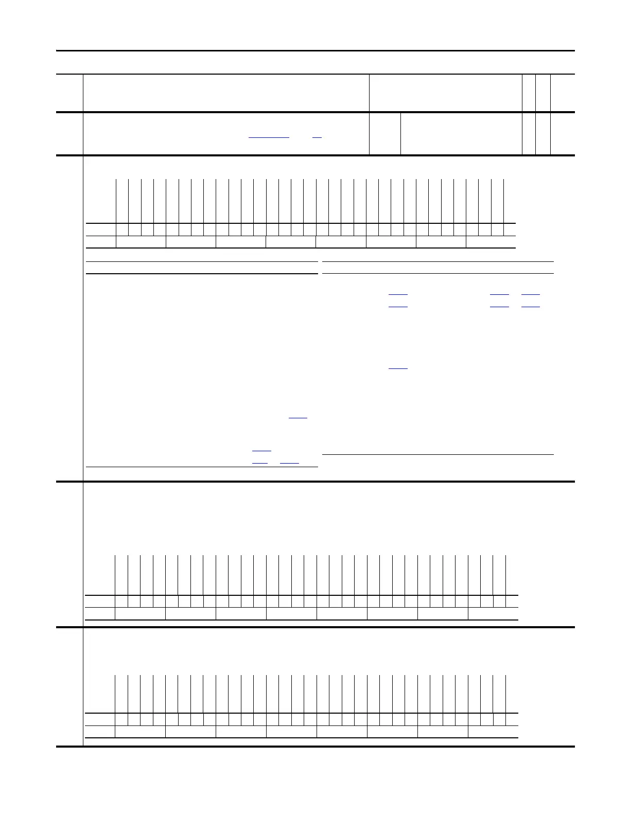
155 Logic Status
Displays the status - condition of the drive.
156 Start Inhibits
Indicates which condition is preventing the drive from starting or running.
• Bit 16 “GateShutDown” is set when the shunt jumper in the 16-15 position on the Main Control board is missing and a Safe-Off option board is not present.
• Bit 17 “SafeOff Enbl” is set when the HW Enable jumper (P22) is in the Bypass position (on pins 1&3) and the Safe-Off option board is present. A HW Enable is required when a safe-off board is
used.
• Bit 21 “Sleep Stop” is set when the sleep mode has stopped the drive.
• Bit 22 “Sleep Config” is set when sleep mode has not been setup correctly. Check the sleep/wake levels and digital input configuration.
Note: Bit 18 “MC Config” was added to this parameter for firmware version 2.003. Added bit 20 “High BusVolt” for firmware version 4.001. Bits 21 and 22 were added for firmware version 5.002.
157 Logic Ctrl State
Indicates which logic control functions are enabled.
• Bit 22 “S Tst FulSpd” set to “1” indicates that the Slip Auto Tune function is active
• Bit 23 “Slip Test En” set to “1” indicates that the drive is at speed for the Auto Tune function.
Notes: Bits 22 and 23 were added for firmware version 3.001. Bit 14 “DC Brake En” is not functional.
No. Name
Description
Values
Linkable
Read-Write
Data Type
Options
LogixPresent
Spd Ref Act2
Spd Ref Act1
Spd Ref Act0
Reserved
RunCommanded
Start Active
PositionMode
Speed Mode
Torque Mode
Hw Enable On
Spd Commis
MC Commis
MC Active
Above Setpt2
At Setpt 1
Enable On
At Setpt Spd
At Zero Spd
Tach Loss Sw
At Limit
Ready
Flash Mode
Alarm
Faulted
Jogging
Decelerating
Accelerating
Actual Dir
Command Dir
Running
Active
Default 00000000000000000000000000000000
Bit 313029282726252423222120191817161514131211109 8 7 6 5 4 3 2 1 0
Bit Name Current Function Bit Name Current Function
0 Active Drive is controlling motor 15 Enable On
1 Running Run command received & controlling motor 16 At Setpt 1 Par
172 value is within limits defined by Par 173 and Par 174
2 Command Dir Commanded direction is forward 17 Above Setpt 2 Par 175 value is within limits defined by Par 176 and Par 177
3 Actual Dir Actual motor direction is forward 18 MC Active Drive is controlling motor (same as enabled)
4 Accelerating Motor is increasing speed 19 MC Commis Motor control commissioning in progress
5 Decelerating Motor is decreasing speed 20 Spd Commis Speed control commissioning in progress
6 Jogging Jog command received & controlling motor 21 Hw Enable On
7 Faulted Exception event that causes a fault has occurred 22 Torque Mode Par
110 value is 2, 3, 4, 5 or 6
8 Alarm Exception event that causes an alarm has occurred 23 Speed Mode Par 110 value is 1 & position control is not enabled
9 Flash Mode Flash upgrade in progress 24 Position Mode Position control active & Par 110 value is not 2, 3, 4, 5 or 6
10 Ready Enable input is high & drive is fault free 25 Start Active Start command received & controlling motor
11 At Limit Speed, Power, Current or Torque is being limited, refer to Par
304 26 Command Run Run command received
12 Tach Loss SW
Failure is detected in primary speed or position feedback device &
drive has switched to secondary device 28-30 Spd Ref Act1-3
13 At Zero Spd Speed feedback is within limits defined in Par
160 31 LogixPresent
14 At Setpt Spd Speed feedback is within limits defined in Par
41 and Par 171
0 = False
1 = True
Options
Reserved
Reserved
Reserved
Reserved
Reserved
Reserved
Reserved
Reserved
Reserved
Sleep Config
Sleep Stop
High BusVolt
Reserved
MC Config
SafeOff Enbl
GateShutDown
PositFdbkSel
PM Mtr Fdbk
Motin Shtdwn
DigIn Config
Bus PreChrg
Encoder PPR
Jog
Start
Flash Upgrd
Power EE
Power Loss
SW I Lim Stp
SW Coast Stp
SW Ramp Stop
No Enable
Faulted
Default xxxxxxxxx000x0000000000000000000
Bit 313029282726252423222120191817161514131211109876543210
0 = False
1 = True
Options
ProcsTrim En
Cmd Dir Upol
Lgx I/O Cnx
Lgx Run Mode
Reserved
VP Gate Enbl
MC Gate Enbl
Ramp Hold
Slip Test En
S Tst FulSpd
PM Offset Rq
Mtr Dir Req
Pwr Diag Req
MC Atune Req
FTD Ramp EN
MC En Req
RThru Flux
DC Brake En
Mtr Sim Mode
RThru Coast
CurrRef En
Forced Spd
Trq Ref En
Spd Reg En
SReg IntgHld
CurLim Stop
J Tst FulSpd
Inert Tst En
PositionEnbl
SRef SCrv En
SRef Ramp En
Spd Ref En
Default 0000x000000000000000000000000000
Bit 313029282726252423222120191817161514131211109876543210
0 = False
1 = True
 Loading...


