44 Rockwell Automation Publication 20D-PM001D-EN-P - March 2019
Chapter 2 Programming and Parameters
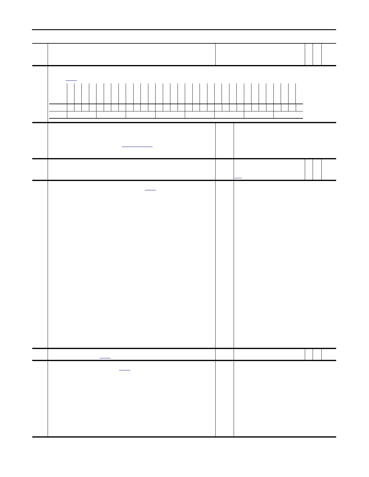
158 Drive Logic Rslt
This is the logic output of the logic parser that combines the outputs from the DPI ports and the DriveLogix controller to determine drive control based on the masks and owners. The control bits are
reflected in Par
152 [Applied LogicCmd] bits 16-31.
159 DigIn ConfigStat
This parameter indicates the status of the digital inputs.
• If 8 “Sleep Config” is displayed, the sleep mode has not been set up correctly. Check the values of parameters
280 [Wake Level] and 282 [Sleep Level] to verify that they are not set outside the bounds of the analog input.
Also verify the digital input configuration. See Figure 9 on page 170
for more information on Sleep / Wake
Mode configuration.
Note: Value 8 “Sleep Config” was added for firmware version 5.002.
Default:
Options:
0 =
0 =
1 =
2 =
3 =
8 =
“DigIn Ok”
“DigIn Ok” 4 = “Strt+UnLatch”
“2 Run/Starts” 5 = “2 Jog1's”
“Start NoStop” 6 = “2 Jog2's”
“Run+Latched” 7 = “2Fwd's/Rev's”
“Sleep Config”
160 Zero Speed Lim
Establishes a band around zero speed that is used to determine when the drive considers the motor to be at zero
speed.
Default:
Min/Max:
Units:
Scale:
17.6400
0.0000/882.0000
rpm
Par
4 [Motor NP RPM] = 1.0 P.U.
Y
RW Real
161 Logic TP Sel
Enter or write a value to select logic status indication displayed in Par 162 [Logic TP Data].
Default:
Options:
0 =
0 =
1 =
2 =
3 =
4 =
5 =
6 =
7 =
8 =
9 =
10 =
11 =
12 =
13 =
14 =
15 =
16 =
17 =
18 =
19 =
20 =
21 =
22 =
23 =
24 =
25 =
26 =
27 =
“Zero”
“Zero” 28 = “Sys Friction”
“Avg Spd Ref” 29 = “Iq proc time”
“Avg Spd Fdbk” 30 = “Enable Inhib”
“LastStopMode” 31 = “DI Src Index”
-(0=None) 32 = “DI SrcRevIdx”
-(1=Coast) 33 = “DI TrendTrig”
-(2=Current Limit) 34 = “DI Prchg Ena”
-(3=Ramp) 35 = “Enable State”
-(4=Torque Mode) 36 = “LID Revision”
“Spd Ref Sel” 37 = “DI MOP Incr”
“Start State” 38 = “DI MOP Decr”
“Run State” 39 = “DI MOP Reset”
“Stop State” 40 = “Cmd Term Blk”
“PrChrg Logic” 41 = “Cmd DPI 1”
“Meas State” 42 = “Cmd DPI 2”
“Data State” 43 = “Cmd DPI 3”
“Diag State” 44 = “Cmd DPI 4”
“MC CalcState” 45 = “Cmd DPI 5”
“Task 1 time” 46 = “Cmd DPI 6”
“Task 1 max” 47 = “Cmd ELC”
“Task 2 time” 48 = “Cmd Debugger”
“Task 2 max” 49 = “Reserved”
“Task 3 time” 50 = “SelSw Posit”
“Task 3 max” 51 = “DI SelSw 00”
“BkGnd Time” 52 = “DI SelSw 01”
“BkGnd Max” 53 = “DI SelSw 02”
“Task 1 %” 54 = “DI SelSw 03”
“Task 2 %” 55 = “Ids Motoring”
“Task 3 %” 56 = “IqsRef Motor”
“BkGnd %” 57 = “Ids Regen”
“RThru State” 58 = “IqsRef Regen”
“RThru Timer”
“Health State”
162 Logic TP Data
Displays the indication selected by Par 161 [Logic TP Sel].
Default:
Min/Max:
0.0000
-/+2200000000.0000
RO Real
163 Stop Oper TP Sel
Enter or write a value to select data displayed in Par 164 [StpOper TPData] at the time of the last initiated stop.
Default:
Options:
0 =
0 =
1 =
2 =
3 =
4 =
5 =
6 =
7 =
8 =
9 =
10 =
11 =
12 =
13 =
“Zero”
“Zero” 14 = “ZM1 Spd Fdbk”
“Logic State” 15 = “Speed Ref”
“Logic Input” 16 = “Avg Spd Ref”
“Lcl In State” 17 = “ZM1 Spd Ref”
“Logic Status” 18 = “SReg PI Out”
“Run Inhibit” 19 = “Trq Ref”
“Logic Ctrl” 20 = “TrqRef Stat”
“Mtr Ctrl Cmd” 21 = “DC Bus Volts”
“Mtr Ctrl Ack” 22 = “Motor Volts”
“Reserved” 23 = “Mtr Current”
“Flt Status 1” 24 = “Motor Flux”
“Flt Status 2” 25 = “Motor Freq”
“Motor Speed” 26 = “Motor Power”
“Avg Spd Fdbk” 27 = “Flt Status 3”
No. Name
Description
Values
Linkable
Read-Write
Data Type
Options
Reserved
Spd Ref Sel2
Spd Ref Sel1
Spd Ref Sel0
Reserved
Reserved
Coast Stop
CurrLim Stop
Jog 2
Reserved
Reverse
Forward
Clear Fault
Jog 1
Start
Normal Stop
Reserved
Spd Ref Sel2
Spd Ref Sel1
Spd Ref Sel0
Reserved
Reserved
Coast Stop
CurrLim Stop
Jog 2
Reserved
Reverse
Forward
Clear Fault
Jog 1
Start
Normal Stop
Default x000xx000x000000x000xx000x000000
Bit 313029282726252423222120191817161514131211109876543210
0 = False
1 = True
 Loading...


