48 Rockwell Automation Publication 20D-PM001D-EN-P - March 2019
Chapter 2 Programming and Parameters
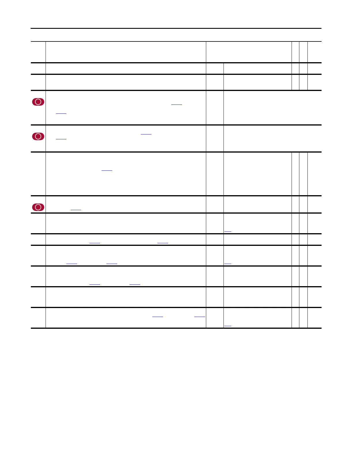
219 PeakDetect2 Out
Output from the second peak/level detector.
Default:
Min/Max:
0.00
0.00/1200.00
RO Real
221 Load Estimate
Displays the estimated load torque, which is the side effect of the speed observer and does not include torque to
accelerate or decelerate the motor if the inertia input is correct. The value is provided for display purposes.
Default:
Min/Max:
Units:
0.0
-/+8.0 P.U.
P. U .
RO Real
222 Mtr Fdbk Sel Pri
Selects primary feedback device. The primary feedback device configuration must not be set to fault on an event
in order to allow operational feedback switch over to the alternate feedback device set in Par
223 [Mtr Fdbk Sel
Alt].
Notes: Par 485 [Motor Ctrl Mode] must be set to FOC for Sensorless feedback selection to be active. Selection 5 is
only available when compatible feedback option card is installed. This parameter was changed to non-linkable for
firmware version 3.001.
Default:
Options:
0 =
0 =
1 =
2 =
3 =
“Encoder 0”
“Encoder 0” 4 = “Motor Sim”
“Encoder 1” 5 = “FB Opt Port0”
“Sensorless”
“Reserved”
223 Mtr Fdbk Sel Alt
Selects alternate feedback device if the feedback device selected in Par 222 [Mtr Fdbk Sel Pri] fails.
Notes: Par
485 [Motor Ctrl Mode] must be set to FOC for Sensorless feedback selection to be active. Selection 5 is
only available when compatible feedback option card is installed. This parameter was changed to non-linkable for
firmware version 3.001.
Default:
Options:
2 =
0 =
1 =
2 =
3 =
“Sensorless”
“Encoder 0” 4 = “Motor Sim”
“Encoder 1” 5 = “FB Opt Port0”
“Sensorless”
“Reserved”
224 TachSwitch Level
Sets the detection level for the automatic tach loss switch-over routine. A drop in feedback speed at this percent of
rated speed over 0.5 msec will cause a tach switch from primary to alternate feedback device. This feature is
enabled when bit 16 “Auto Tach Sw” in Par 153 [Control Options] is selected.
Setting this level lower will make the tach switch detection more sensitive and lower the minimum speed at
which a tach switch can occur. Setting this level higher will make the tach switch less sensitive and raise the
minimum speed for tach switch detection.
Note: This parameter was changed to non-linkable for firmware version 3.001.
Default:
Min/Max:
Units:
10.0000
5.0000/25.0000
%
RW Real
225 Virtual Edge/Rev
Set the edges per revolution (EPR) scaling for calculating motor position. Used in the calculation of the position
feedback such as Par 229 [MtrPosit Stimulat].
Default:
Min/Max:
Units:
4096
10/16777216
EPR
RW 32-bit
Integer
226 Motor Speed Est
Displays the estimated motor speed, calculated when the selected feedback is sensorless or when encoderless
ridethrough is enabled.
Default:
Min/Max:
Units:
Scale:
0.0000
-/+14112.0000
rpm
Par
4 [Motor NP RPM] = 1.0 P.U.
RO Real
227 Motor Posit Est
Summation (or integration) of Par 226 [Motor Speed Est] scaled by the value in Par 225 [Virtual Edge/Rev].
Default:
Min/Max:
0
-/+2147483648
RO 32-bit
Integer
228 MtrSpd Simulated
The motor speed output of the motor simulator. The motor simulator provides motor speed information during
setup and troubleshooting when actual motor control is not desired or possible. To use the motor simulator, enter
a value of 4 in Par 222 [Mtr Fdbk Sel Pri] or Par 223 [Mtr Fdbk Sel Alt].
Default:
Min/Max:
Units:
Scale:
0.0000
-/+14112.0000
rpm
Par 4 [Motor NP RPM] = 1.0 P.U.
RO Real
229 MtrPosit Simulat
The motor position output of the motor simulator. The motor simulator provides motor position information
during setup and troubleshooting when actual motor control is not desired or possible. To use the motor
simulator, enter a value of 4 in Par
222 [Mtr Fdbk Sel Pri] or Par 223 [Mtr Fdbk Sel Alt].
Default:
Min/Max:
0
-/+2147483648
RO 32-bit
Integer
230 Encdr0 Position
Displays the position feedback (accumulator) from encoder 0. The value changes by a value of four times (4x) the
Pulses Per Revolution (PPR) rating of the encoder for each full revolution of the encoder shaft. Used by the Velocity
Position Loop (VPL) to close the position loop if position control is selected.
Default:
Min/Max:
0
-/+2147483648
RO 32-bit
Integer
231 Encdr0 Spd Fdbk
Displays the speed feedback from encoder 0. Calculated from the change of Par 230 [Encdr0 Position] and Par 232
[Encoder0 PPR].
Default:
Min/Max:
Units:
Scale:
0.0000
-/+14112.0000
rpm
Par
4 [Motor NP RPM] = 1.0 P.U.
RO Real
No. Name
Description
Values
Linkable
Read-Write
Data Type
 Loading...


