62 Rockwell Automation Publication 20D-PM001D-EN-P - March 2019
Chapter 2 Programming and Parameters
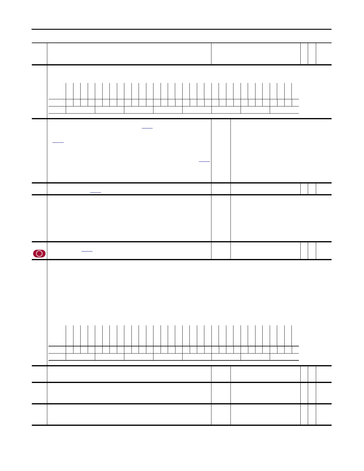
286 Linear1 Status
Indicates faults on the Multi Device Interface (MDI).
Bit 8 “Open Wire” indicates an open wire fault.
287 Linear1 TP Sel
Enter or write a value to select Linear Feedback data displayed in Par 288 [Linear1 TP Data].
• Value 0 - Zero displays a value of zero.
• Value 1 - L1 Edge Time displays the change displays the latency or edge time (the time since the last update of
Par
252 [FB Opt1 Posit]).
• Value 2 - L1 dEdge displays the change in Par 252 [FB Opt1 Posit] since the last feedback sample.
• Value 3 - L1 DTime displays the change in time since the last feedback sample Note the sample rate is 10,000
counts per second (10 Mhz).
• Value 4 - L1 EPR displays the change in edges per motor revolution. This number is the same value in Par
290
[Linear1 CPR].
• Value 5 - Edge Mode should always display a zero (0).
• Value 6 - L1 nMax displays the numerator term for speed calculation. This number divided by change in time
(TP3) is the calculated per unit speed for the linear feedback sensor.
Default:
Options:
0 =
0 =
1 =
2 =
3 =
“Zero”
“Zero” 4 = “L1 EPR”
“L1 Edge Time” 5 = “L1 Edge Mode”
“L1 dEdge” 6 = “L1 nMax”
“L1 dTime” 7 = “L1 Delta2Err”
288 Linear1 TP Data
Displays the data selected by Par 287 [Linear1 TP Sel].
Default:
Min/Max:
0
-/+32768
RO 16-bit
Integer
289 Lin1 Update Rate
Sets the sample rate for the linear channel on the Multi Device Interface (MDI) feedback option.
Default:
Options:
2 =
0 =
1 =
2 =
3 =
4 =
5 =
6 =
7 =
“1.0 msec”
“8.0 msec” 8 = “4.0 msec”
“0.5 msec” 9 = “4.5 msec”
“1.0 msec” 10 = “5.0 msec”
“1.5 msec” 11 = “5.5 msec”
“2.0 msec” 12 = ”6.0 msec”
“2.5 msec” 13 = “6.5 msec”
“3.0 msec” 14 = “7.0 msec”
“3.5 msec” 15 = “7.5 msec”
290 Linear1 CPR
Specifies the change in Par 252 [FB Opt1 Posit] for one revolution of the motor shaft. This value is used to scale
the calculated speed, based on the change in feedback position. Units are count per motor revolution (CPR).
Default:
Min/Max:
Units:
1000
10/100000
CPR
RW 32-bit
Integer
291 Lin1Stahl Status
Displays the status of the Stahl linear encoder. The Stahl linear encoder works with the MDI option card.
• Bit 8 “No Data Read” indicates that no data can be read from the encoder
•Bit 9 “Alarm Optics” displays an alarm when fiber optics require cleaning
• Bit 10 “Out of Range” indicates that the encoder read count is at the maximum value (524,287)
• Bit 11 “ErrBits16-31” displays a diagnostic error code (refer to bits 16-31)
• Bit 16 “Fault Optics” indicates that the read head for fiber optic cable must be cleaned or replaced
• Bit 17 “Read Head” indicates that the fiber optic cable read head must be checked, aligned or replaced
• Bit 18 “RAM error” indicates that the fiber optic cable read head must be replaced
• Bit19 “EPROM error” indicates that there is an error with the communication module, replace read head.
• Bit 20 “ROM error” indicates, replace read head.
• Bit 22 “No Position” Cycle power to Stahl read head.
296 Motor Freq Ref
Currently not used.
Note: This parameter was added for firmware version 2.003.
Default:
Min/Max:
Units:
0.00
-/+500.00
Hz
RO Real
297 Output Curr Disp
Displays measured RMS motor current with a resolution of 1/10 amperes.
Default:
Min/Max:
Units:
Scale:
0.0
0.0/9999.9
A
x 10
RO 32-bit
Integer
298 Elapsed Run Time
Displays the total time that the drive has been running (inverter power devices active) with a resolution of 1/10
hour. This parameter is saved in power EE non-volatile memory. The value in this parameter can be changed
(written to) by the user.
Default:
Min/Max:
Units:
Scale:
0.0
0.0/429496736.0
hr
x 10
RW 32-bit
Integer
No. Name
Description
Values
Linkable
Read-Write
Data Type
Options
Reserved
Reserved
Reserved
Reserved
Reserved
Reserved
Reserved
Reserved
Reserved
Reserved
Reserved
Reserved
Reserved
Reserved
Reserved
Reserved
Reserved
Reserved
Reserved
Reserved
Reserved
Reserved
Reserved
Open Wire
Reserved
Reserved
Reserved
Reserved
Reserved
Reserved
Reserved
Reserved
Default xxxxxxxxxxxxxxxxxxxxxxx0xxxxxxxx
Bit 313029282726252423222120191817161514131211109876543210
0 = False
1 = True
Options
Reserved
Reserved
Reserved
Reserved
Reserved
Reserved
Reserved
Reserved
Reserved
No Position
Reserved
ROM error
EPROM error
RAM error
Read Head
Fault Optics
Reserved
Reserved
Reserved
Reserved
ErrBits16-31
Out of Range
Alarm Optics
No Data Read
Reserved
Reserved
Reserved
Reserved
Reserved
Reserved
Reserved
Reserved
Default xxxxxxxxx0x00000xxxx0000xxxxxxxx
Bit 313029282726252423222120191817161514131211109876543210
0 = False
1 = True
 Loading...


