36 Rockwell Automation Publication 750-IN118A-EN-P - May 2021
Chapter 2 Prepare for Installation
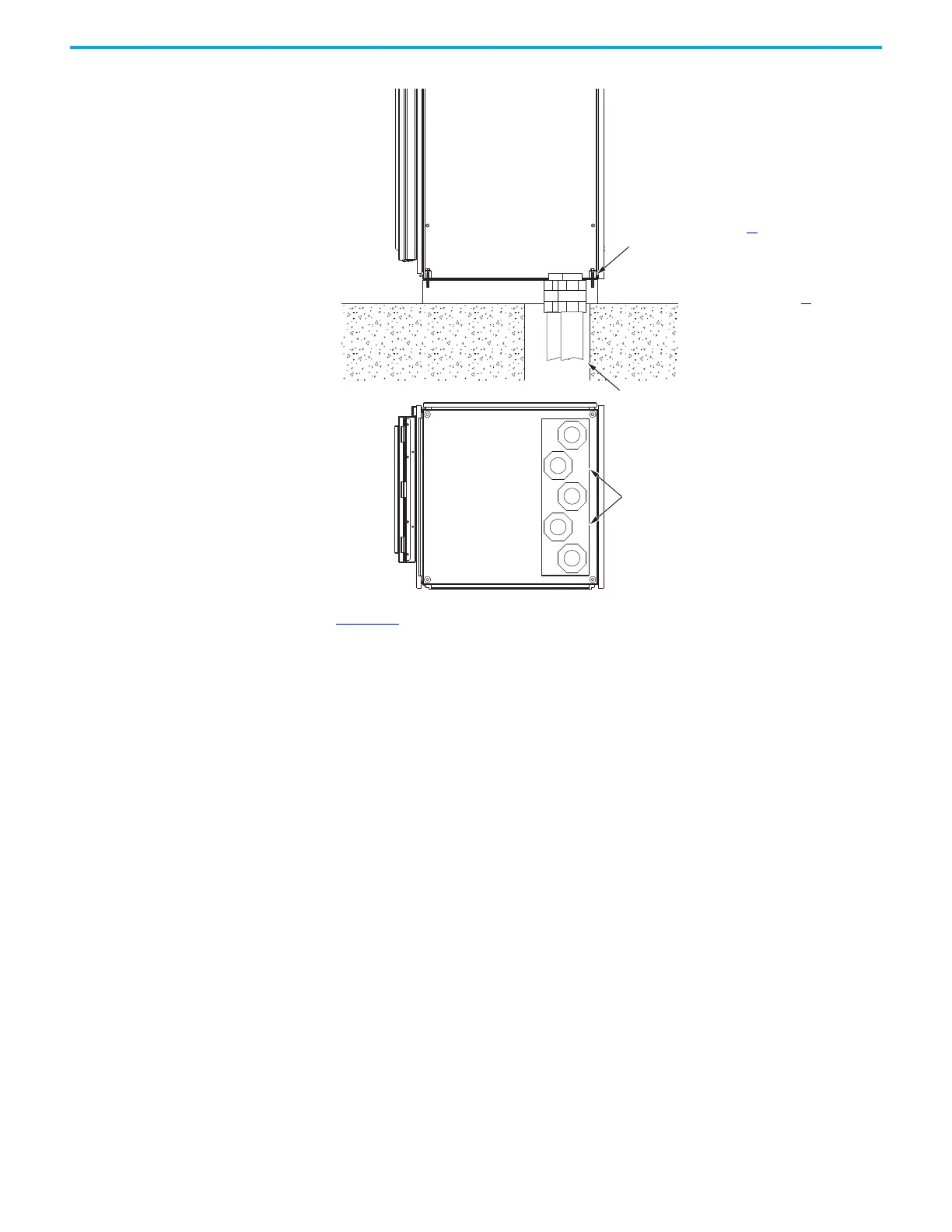
Figure 33 - Cross-section View of Cable Bottom Entry and Exit
Figure 33 shows a drive power bay as an example, but is applicable to all bottom
entry or bottom exit bays.
Front Rear
Conduit
Mounting screws (see page 44
)
Mounting surface (see page 35
)
Bottom view
Recommended gland or conduit hole pattern.
Use the locations marked on the plate.
Side view
Floor mounting hardware

 Loading...


