20
2
3
7 INSTALLATION
The installaon must be performed by qualied and experienced personnel,
in full compliance with the regulaons.
For General instrucons for installaon and maintenance, refer to secon
3 of this installaon manual.
7.1) Preparaon and installaon of the foundaon plate
The following illustraons are for illustrave purposes only, as the space
for securing the automaon and the accessories varies depending on
the dimensions. It is therefore the installer who selects the most suitable
soluon for analysing the spaces and the surrounding environment, ensure
that there are no impediments to the movement of the bar, such as trees,
electricity cables, street lights or other things and carefully selecng the
most suitable automaon for installaon to be carried out, based on the
width of the passage and the limits of use.
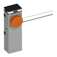
Assemble the 4 anchors complete with nuts; warning: the lower nut must
be screwed to the end of the thread, so as to comply with the "Z" minimum
height of 40 mm as shown in Fig.2. Run the foundaon hole with the
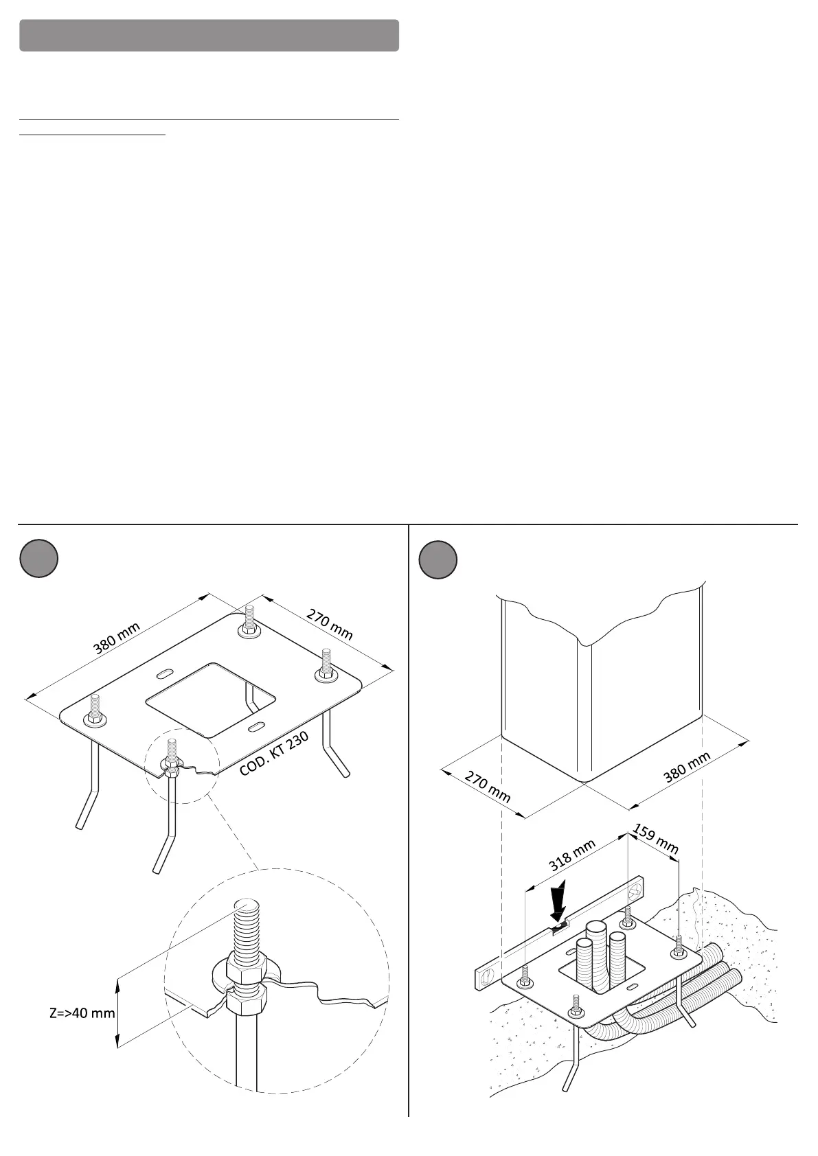
following minimum dimensions: one metre by one metre and a depth of 0.3
metres, to accommodate the "KT230" foundaon plate, as shown in Fig 3.
Posion the conduit for the passage of the electric cables.
Perform an adequately reinforced concrete cast with iron cages, ood the
central foundaon plate so it is ush with the surface, perfectly level and
parallel to the structure of the barrier and the bar, which is to be installed
later, aer the concrete is completely set, as shown in Fig. 3.
The concrete foundaon must be made following the standard rules, by
competent personnel.
7.2) Installing the barrier assembly
Aer successfully laying the foundaon plate (7.1), install the body of the
barrier.
Remove the washers and nuts screwed onto the e rods on the "KT230"
foundaon plate that was previously cemented, as shown in Fig 4.
Unscrew the 2 screws xed on the head of the case, on the side where the
bar is to be xed, as shown in Fig 5.
Open the inspecon door through the appropriate lock by turning the key
90° clockwise, as shown in Fig. 6.
Manually li the head, disconnect the grounding cable dedicated to the
head from the concentrator; support the head on a suitable surface so as to
avoid impacts or electrical damage.
Aer also disconnecng the grounding cable dedicated to the inspecon
door from the concentrator (Fig. 7), it is possible to open the door by
removing it from its slot.
Support the case on top of the "KT230" foundaon plate so that the
cemented e rods pass through the 4 sloed holes located in the 4 corners
of the base.
Insert the washers and nuts that were removed onto the e bars, as shown
in Fig. 8; orient the case as desired, using the slots of the base and then
ghten the nuts rmly for the barrier body case in a stable manner.
Important Note:
In terms of electronics, the barrier is set in the factory for installaon on
the right (DX), when looking at the gate from the inside. In the event that
installaon is to be done on the le (SX)follow the instrucons given in the
bar assembly secon.
 Loading...