25
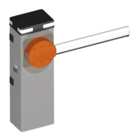
11 INSTALLING THE FLASHING LED CIRCUIT OF THE BARRIER
ASSEMBLY HEAD (AG / BLED)
To install the 4-quadrant ashing LED on the head of the barrier assembly,
proceed as follows and what is shown in Figure 19.
- Cut o the power from the automaon, insert the key and release
the inspecon door sealing hook aached to automaon cover.
- Remove the 2 xing screws of the head of the barrier and
remove it completely, paying aenon to the ground wire, which must be
disconnected.
- By overturning the complete head we can see the slots where
the 4-quadrant LED circuit should be installed, which must be correctly
posioned in their slots, using the 2 xing screws for each quadrant supplied,
avoiding passing the cables between the quadrants on the side where the
slot of the latch of the inspecon door is located. See point "X".
- The nal part of the 4-quadrant LED circuit is inclusive of the
connecon plug. The wiring is also provided, which must be connected
directly to the control unit. To make this connecon, pass the connecng
cable with the connecon plug to the unit box under the box through the
cable hole and connect it correctly to the unit in the hall dedicated input.
Finally, connect the two connecon plugs to each other.
- Provide power and enter into the programming of the unit AG/
CTRL and in in extended mode, posion yourself in parameter No. 78 and
congure the desired ash mode.
- Tightly and correctly close the cover of the box of the unit,
reposion the aluminium cover of the barrier assembly in the correct
direcon, close and aach the inspecon door and x the two nal screws
of the cover of the aluminium head.
12 CONNECTING THE PHOTOCELLS IN THE BARRIER ASSEMBLY
On both sides of the barrier body, it is possible to install the photocells of
the G90 series and largely the G90/F2ES photocells Pair of photocells for
external sync.
In both sides, the photocells can be installed at two heights of 50 cm or 100
cm from the boom of the column, see Figure 20.
To install the photocell, cut o the power from the barrier, remove the cover
of the head and open the inspecon door.
Posion yourself over the desired photocell, loosen the two screws that hold
the plasc cover from the inside of the barrier body, fasten the photocells
to the side of the barrier cables by passing the cables upwards, avoiding the
wiring in a way that disturbs the movement of the automaon. Use the cable
gland, located under the box containing the control unit and connect it to
the unit into the dedicated input.
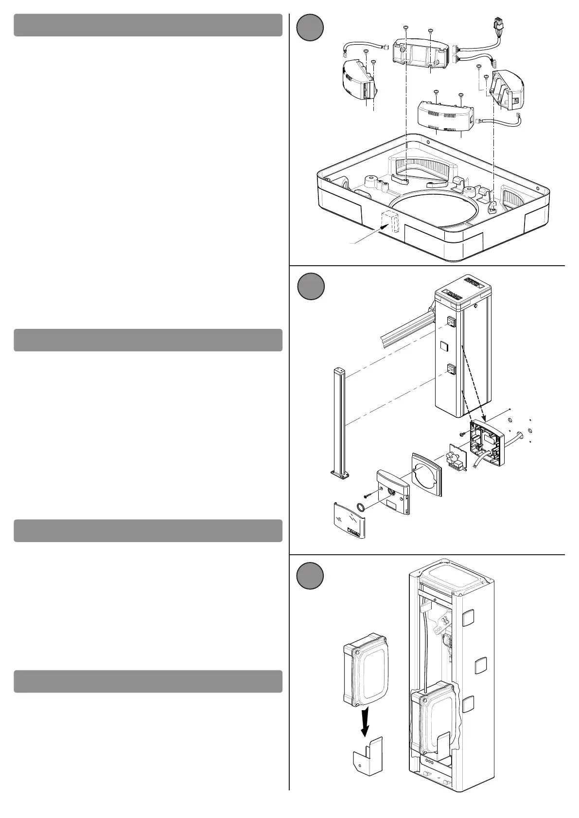
The baery module B71/BCHP should be connected and installed inside the
cabinet, it should be carried out as shown in Fig. 21.
The galvanized steel support of the baery holder box must be inserng in
one of the two side niches on the right or le. Please note that it should be
assembled on the opposite side of the balance spring.
To electrically connect the baery to the unit, consult the instrucons
manual of the installed baery module.
Ensure the baery's power cable so that it does not suer damage during
the movement of the mechanical parts inside the cabinet.
For connecons and programming of the electronic control unit, refer to the
instrucon manual of the installed control unit, AG/CTRL supplied inside the
automac barrier, together with the installaon manual in queson.
13 INSTALLATION AND CONNECTION OF THE EMERGENCY
BATTERIES MODULE
14 CONNECTING AND PROGRAMMING THE CONTROL UNIT
X
19
TX
TX
RX
RX
20
21
 Loading...