23
123
ABC
11
12
13
14
15
A A
B
B
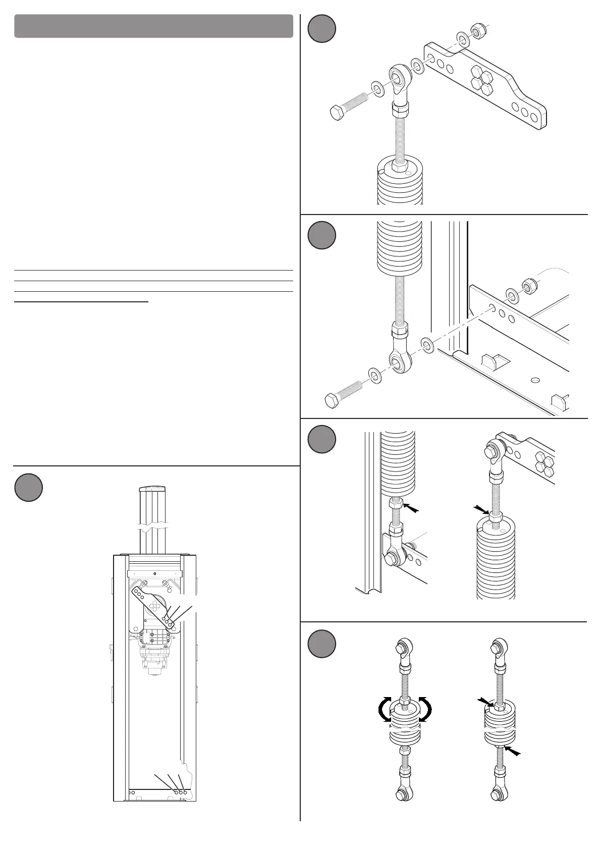
8 BAR BALANCING SPRING
8.1) Installaon and balancing of the spring of the bar
To balance the forces in play and for proper operaon of the automac
barrier, it is necessary to install a balancing spring.
Depending on the length of the bar that you intend to install, choose
between two dierent models of the following springs:
AG/SP/72: Spring for bars of up to 4 metres.
AG/SP/83: Spring for bars up to 6 metres in either a single bar or 2 joined
bars.
To assemble the spring, choose a pair of holes from the steel supports
highlighted in Fig 11 (e.g. A-1, A-2 or B-2 etc.), paying aenon to assemble
the spring on the right side, based on the posion of the bar. Warning: using
holes posioned closer or further away from the centre of the arm aects
the tension of the spring, for example, if you use hole No. 3, the spring is
more stretched.
Secure the spring by screwing it into steel arm, in the arranged holes, using
the supplied screws, following the diagram in Fig. 12.
Secure the spring to the xed structure, on the steel beam at the base of
the column of the barrier using the supplied screws, following the diagram
in Fig. 13.
Note that both springs are indicated with a red or yellow colour in the
respecve hubs, according to the diameter type of the spring. So pay
aenon during the installaon, ensuring that the coloured part of the
spring is always posioned upward.
8.2) Adjusng the spring tension
When the automaon is released (see Chapter 10), manually move the bar
by 45° and release it. If it opens or closes, it means that the balance is not
opmally set. This depends on the length of the bar and the accessories
installed in it and therefore on its own weight.
For opmum results, it is necessary to adjust the tension of the previously
installed spring, inially by unscrewing the lock nuts of the spring, shown
in Fig. 14, both the one above and the one below and manually rotate the
spring (Fig. 15 A) in a clockwise or anclockwise direcon to decrease or
increase the tension; when the adjustment of the tension of the spring is
opmal, it is necessary to rmly ghten the locking nuts of the spring (Fig.
15 B).
 Loading...