24
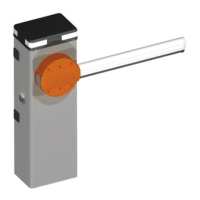
9 ADJUSTING THE MECHANICAL STOP IN OPENING AND CLOSING
The automaon is provided with mechanical stops in opening and closing
which must be adjusted with precision, following the procedure indicated
below.
Warning: Fig. 16 shows the installaon of a LEFT automaon; in the event of
a RIGHT installaon, it is necessary to adjust in a specular fashion.
Unlock the automasm with the supplied key (see Chapter No. 10).
Adjust the screws of the mechanical stop in closing (Fig. 16 point A) to
horizontally adjust the bar in a closed posion. Adjust the screws of the
mechanical stop in opening (Fig. 16 point B) to vercally adjust the bar in
an open posion.
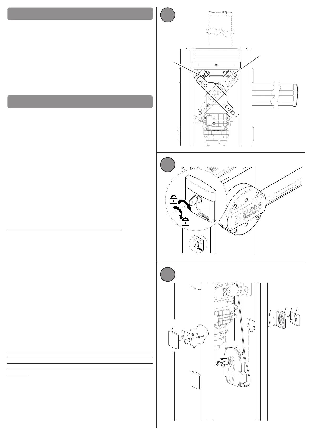
10 AUTOMATISM RELEASE
In some situaons, such as in the event of a power outage or scheduled or
extraordinary maintenance, it is necessary to release the automaon.
The operaon of the release of the automaon must never be carried out
when the bar is in moon and it is therefore necessary to ensure that the bar
is stopped and in the closed posion (horizontal).
Moreover, ensure that at the me of release, no person, animal, item or
vehicle is passing by or stopped within range of automaon.
To release it, it is necessary to insert the release key supplied on the lock,
which is located on a side of the case (Fig. 17), and make 2 complete turns
anclockwise (2 x 360°).
To lock the automasm again, it is necessary to turn the key clockwise and
make 2 full turns (2 x 360°).
In the case of incorrect installaon or improper securing of the bar in its slot
during assembly, or in the case of a bar that has been broken by an accident
or another cause, the springs installed under tension no longer guarantee
the balancing set. Pay aenon as this situaon can cause sudden rotaon
of the bar, during the release operaon, and therefore pose a potenal
hazard to the user.
10.1) Assembly of the release system on the opposite side
The release system is assembled in the factory on one of the two sides of the
case. It is possible to disassemble and reassemble it on the opposite side, by
following the procedure shown in Fig 18:
Open the inspecon door of the automaon case.
Unscrew the xing screws of the plasc cover (A) on the side on which you
want to install the release.
Remove the plasc cover plate (B) of the release system, by leveraging the
four side latches; unscrew the two self-tapping screws (C) and remove the
aluminium front (D); remove the four M5 nuts (E).
Now the release system is no longer secured to the automation structure
and so release is possible, by pushing the steel joint outwards (F) by
compressing the spring, and then rotating the same joint by 45° (G), finding
the self-retaining point.
In order to assist and to check the correct assembly of the release, on the
opposite side two RED and GREEN caps have been included in the rotaon
plugs.
Note: To check the correct assembly of the release independently of the
side, check that the two green plugs are facing the operator's side if the
barrier is blocked. In the case where the green caps are facing the opposite
side of the operator, this means that the release has been assembled
otherwise.
Then, remove the release box and assemble it on the opposite side, paying
aenon to the safety wiring.
For the nal xing, follow the instrucons in reverse. Lastly, complete the
task by xing the plasc cover (A) on the side where the release was inially
assembled.
A
B
16
2 x 360°
2 x 360°
17
18
A
B
C
D
E
F
G
 Loading...