22
9
10
CA
E
B
B
F
D
G
H
K
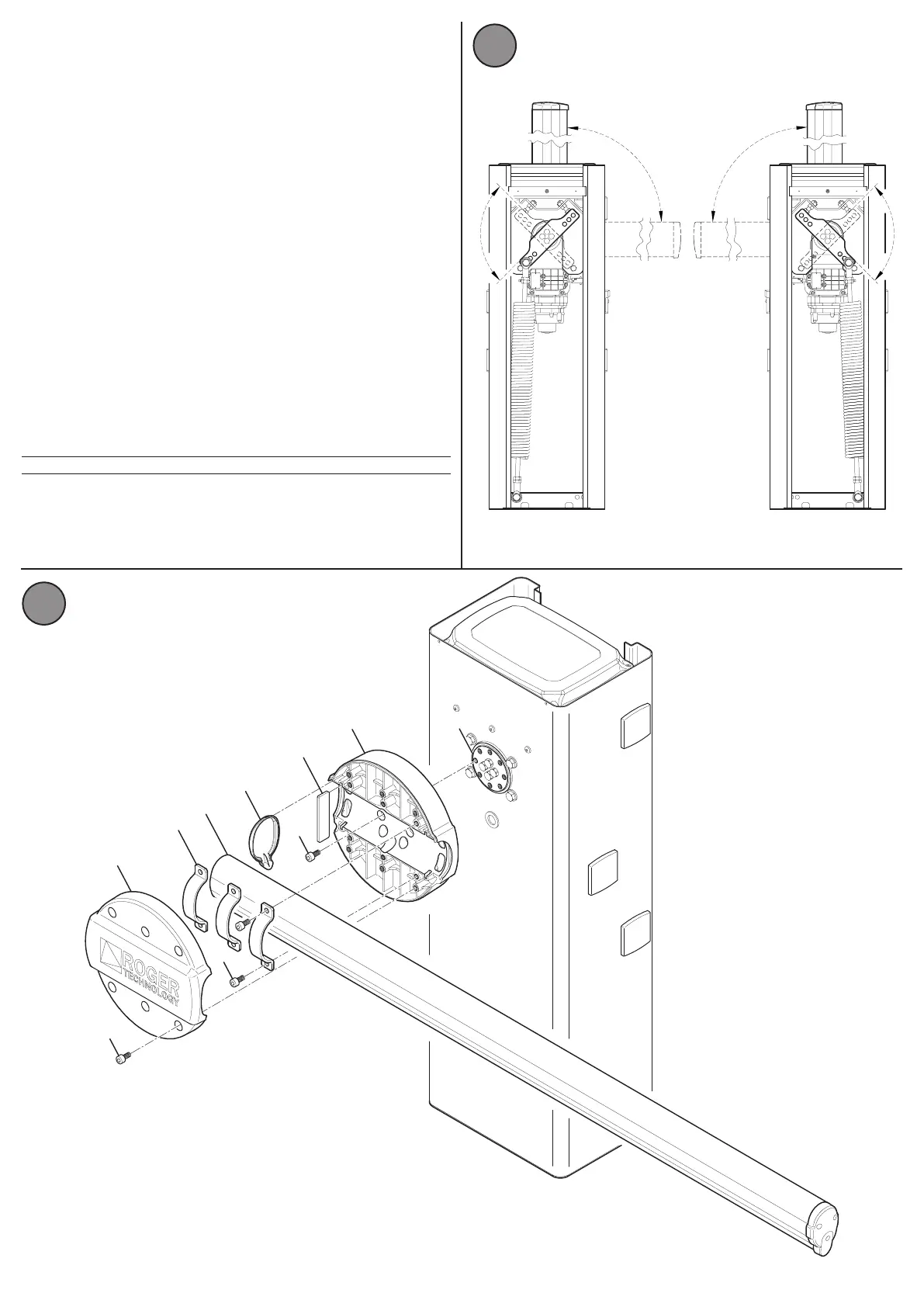
7.3) Installaon of the bar
Before installing the bar, ensure that the internal arm for securing the spring is
oriented in the correct direcon, according to the arrangement of the barrier
of a right or le installaon, as shown in
Fig 9.
To install a bar, proceed as described:
Release the geared motor through the appropriate release key supplied
with the barrier (see Chapter 10); manually rotate the arm unl it reaches
the proper recommended posion, which provides for the ability to vercally
insert the bar, using a removable iron support such as a bar support point,
when inserted
(Ref. "E" Fig. 10). Tighten the geared motor again by turning the key in the
opposite direcon and proceed with the assembly of the bar as shown in Fig 10:
Secure the aluminium bar support base (A)
with 8 galvanized M10 screws
(B)
to the xing ange that comes out of the geared motor (C). Tighten with
adequate strength.
Rest the bar (D)
in its slot and push it in support to the steel plate (E);
apply the
three moulded steel anges (G)
and secure with 6 galvanized M10 screws (B).
Tighten with adequate strength. Posion the plasc end cap in its slot (F). Now
apply the nal aluminium cover (H)
and secure it with 6 steel M10 screws (K).
If necessary, reverse the orientaon as follows:
Release the geared motor (see Chapter 10); manually rotate the arm unl it
reaches the proper posion. Tighten the geared motor by turning the key in
the opposite direcon.
Now remove the cover of (H), loosen the xing ange unl the bar slides freely,
(G), remove the plasc end cap (F) and slide the bar up to the desired posion.
Posion the plasc cap and reaach all previously removed or loosened parts.
Note: For correct conguraon of the le/right opening of the automac
barrier, refer to the of the control unit manual AG / CTRL parameter No. 71.
 Loading...