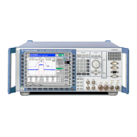
CMU Front and Rear View
1100.4903.12 1.5 E-10
0
12
3
45
6
78
9
.
-
ON / OFF ENTER
1100.0008.02
VARIATION
DATA
FUNCTION SYSTEM
CONTROL
DATA
CTRL
MENU
SELECT
HE LP SETUP
mark
symb
E
F
B
M/µ
µV
W
C
dBµV
k/m
G/n
A
mV
D
1
dB
dBm
UNIT...
EXP/CMP CONT/HALT
RF4 IN
*
abc def
ghi
jkl mno
pqr
stu
vwx yz
_ µ
AF IN AF OUT
VOL
DEL
AUTO
INFO RESET
PRINT
*
#
Ω
AUX 1 AUX 2
SPEECH
AUX 3
DATA 2
13 dBm
MAX
2 W
MAX
50 W
MAX
13 dBm
MAX
RF 3 OUT
RF 2 RF 1
DATA 1
INS
CLR
For future extensions
Signals from/to
speech codec
(option CMU-B52)
Auxiliary input/output
AUX3
AF inputs and outputs
Fig. 1-5 CMU front view connectors
DATA1, DATA2
DATA 1
DATA 2
For future extensions
!
Chapter 8, "Hard-
ware connectors"
AUX 3 and SPEECH
AUX 3
Input/output for timing and external trigger signal
CMU300: External trigger signal for
wired synchronization
!
Chapter 8, "Hard-
ware connectors "
SPEECH
Signals from/to speech codec (option CMU-B52)
!
Chapter 8, "Hard-
ware connectors"
AF connectors
AF IN AF OUT
AUX 1 AUX 2
Connectors for audio signals:
AUX1/2 Additional input/output for audio sig-
nals that may be used in remote con-
trol (secondary audio analyzer)
AF IN/OUT Standard input/output for the (primary)
audio analyzer
Caution: Note the maximum permissible input levels
for all AF connectors according to the data sheet in
order to prevent damage to the instrument!
!
Chapter 4, "Audio
Generator and
Analyzer";
Chapter 8, "Hard-
ware connectors"

 Loading...


