RB48 BROOM
ROSCO - A LeeBoy Company
Maintenance
4.8
MAINTENANCE
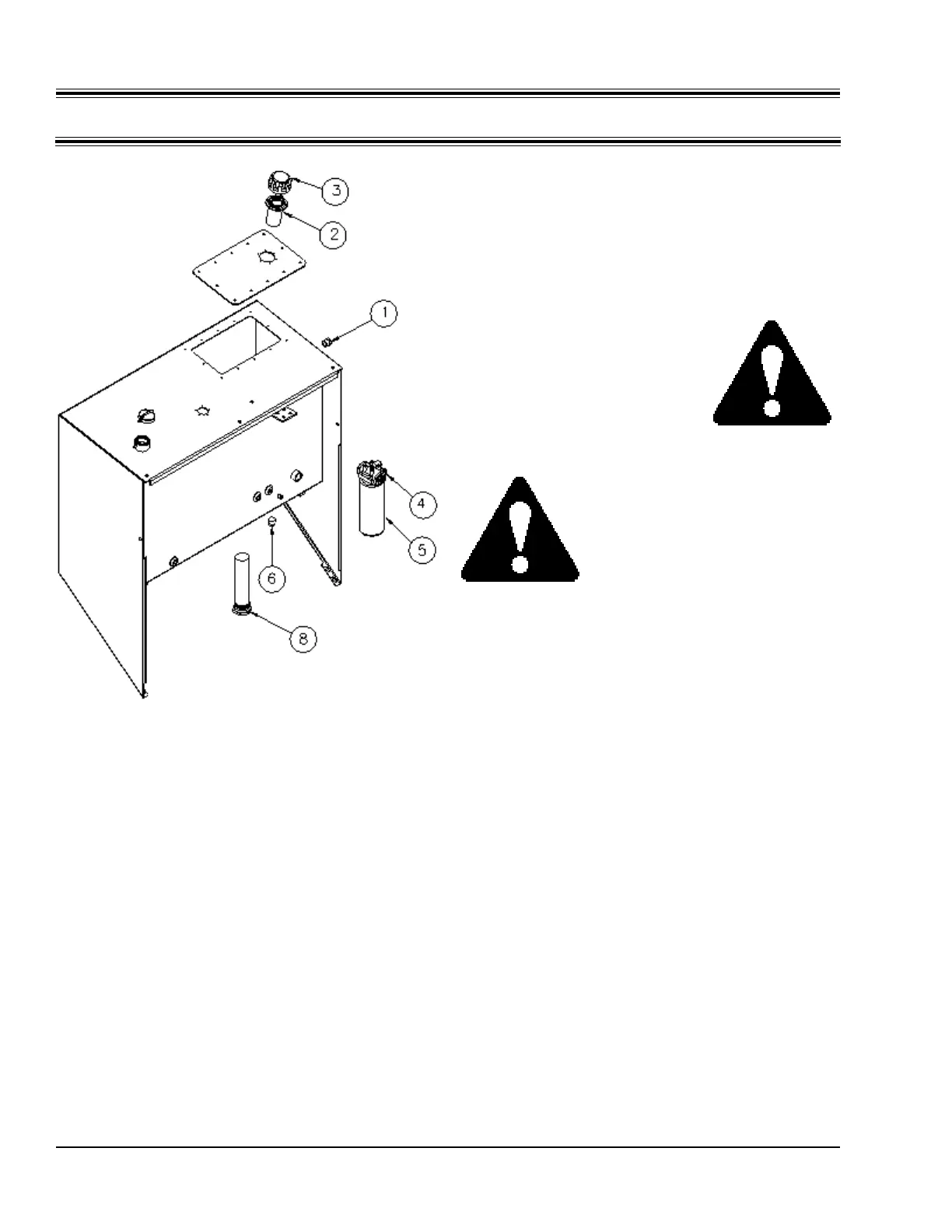
F. Drain and replace hydraulic oil and filter
after the first 100 hours of service, and after every
500 hours of service or seasonally, whichever
comes first. Use genuine Rosco replacement
parts when changing the filter element. Refer to
the Preventive Maintenance Chart at the end of
this section for part number. Drain the hydraulic
oil by removing the plug (6). For convenience, a
customer supplied drain hose can be attached to
drain fluid into a container.
G. The suction strainer (8) should be removed
and cleaned at the 500 hour service interval or
whenever the hydraulic oil is changed. There is no
need to remove and clean suction strainer at the
100 hour service interval.
Hydraulic System Checks
Before each day's use, inspect the ROSCO
Broom for possibile hydraulic leaks. A weekly
check should be performed to make sure that all
hose fittings are secure and tight.
DANGER: Never use your
hand to locate hydraulic leaks.
Hydraulic fluid under pressure
will pierce the skin and is
dangerous. Use a piece of
wood or cardboard to locate
leaks. If hydraulic oil has
pierced the skin, get immediate
medical attention.
DANGER: Always wear eye
protection when inspecting for
leaks in the hydraulic system.
A. If leaking fluid is found, it is probably on the
pressure side of the hydraulic system. Find and
repair the leaking component before starting the
broom.
B. Leaks on the suction side of the hydraulic
system are more difficult to find. Some symptoms
of suction leakage which cause air and dirt to
enter the system are:
- Foaming of hydraulic oil
- Sluggish hydraulic system operation
- Unusual noise in hydraulic pump or motor
This condition is serious since air or dirt
introduced into the hydraulic system causes rapid
component wear and eventual failure.
1. If a suction side leak is suspected, verify
that all reservoir connectors and fittings are
properly tightened.
2. If the problem persists, wrap the suction
side hose and connectors with a high-
quality electrical tape. Start at the pump
inlet(s) and work toward the hydraulic
reservoir.
Figure 4-C
Hydraulic Reservoir