RB48 BROOM
4.9ROSCO - A LeeBoy Company
Maintenance
MAINTENANCE
3. If this technique isolates the leak, replace
the defective hose assembly or fitting. Never
attempt to repair hydraulic hoses and/or leave
tape attached.
C. An operator should inspect the broom
during operation for hydraulic leaks which may
only be noticeable while the unit is running.
Pumps and Motors
The hydraulic pump and motor generally require
no regularly scheduled maintenance. As stated
above, frequent inspection for leaks will indicate
the need for service of these components.
A. Adjusting Priority Relief Valve - The
Priority Circuit on the hydraulic pump supplies the
power steering with approximately 4 GPM of
hydraulic flow. This flow goes to the steering
circuit before any other circuit. Occasionally, it
may be necessary to readjust the Relief Valve
setting. The Priority Relief Valve controls the
maximum operating pressure for the power
steering and brush lift and swing circuits. The
Relief Valve is located in the hydraulic pump
attached to the rear of the hydrostatic pump on the
engine flywheel housing. The following are signs
that the Priority Relief Valve needs adjusting:
- Total or partial loss of steering functions or
hard steering
- Constant noise from hydraulic pump when
using steering or brush lift and swing
- Hydraulic oil overheating
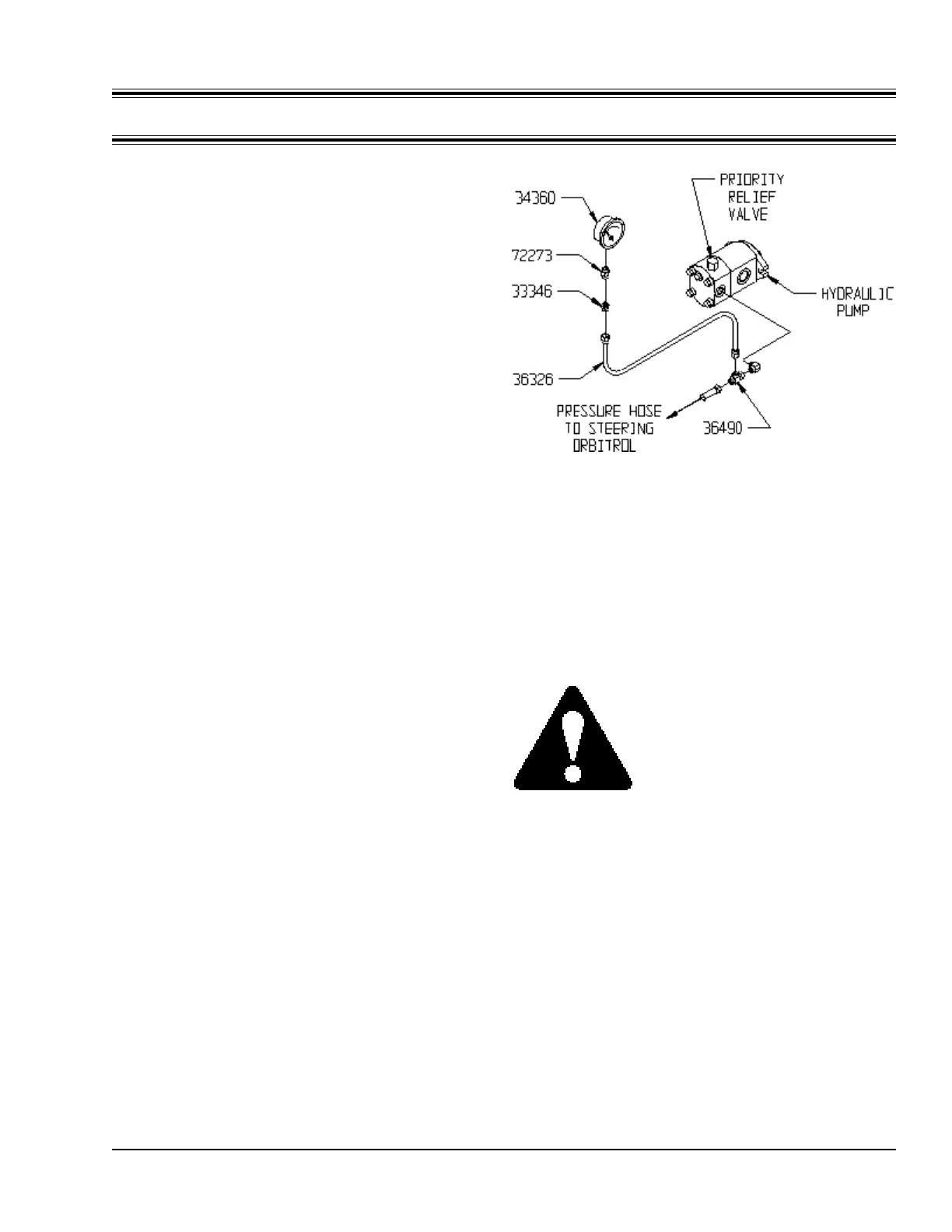
1. Plumb in a 0 to 5000 psi pressure gauge
into the Priority Flow Circuit as shown in
Figure 4-D. Parts needed for this, including
a pressure gauge, can be obtained from
your authorized Rosco dealer. Part
numbers are listed in Figure 4-D.
2. Start the engine and warm the hydraulic oil
to at least 100° F.
Figure 4-D
Setting Priority Relief Valve
3. Set the parking brake and be sure the
transmission is in neutral. Use the foot
brake as an extra precaution.
CAUTION: Use extreme
caution when working under the
ROSCO Broom while adjusting
priority relief pressure. Have
another person who is familiar
with the machine assist you.
4. Increase engine speed to 2500 RPM.
5. Raise the brush using the lift circuit until it
stops. Continue to hold pressure to lift
cylinder until a gauge reading can be
taken.
6. The pressure gauge should read 1500 +/-
50 psi.
7. Adjust relief pressure by removing the
locknut and turning the adjusting screw
clockwise to increase pressure and
counterclockwise to decrease pressure.