RB48 BROOM
ROSCO - A LeeBoy Company
Maintenance
4.10
MAINTENANCE
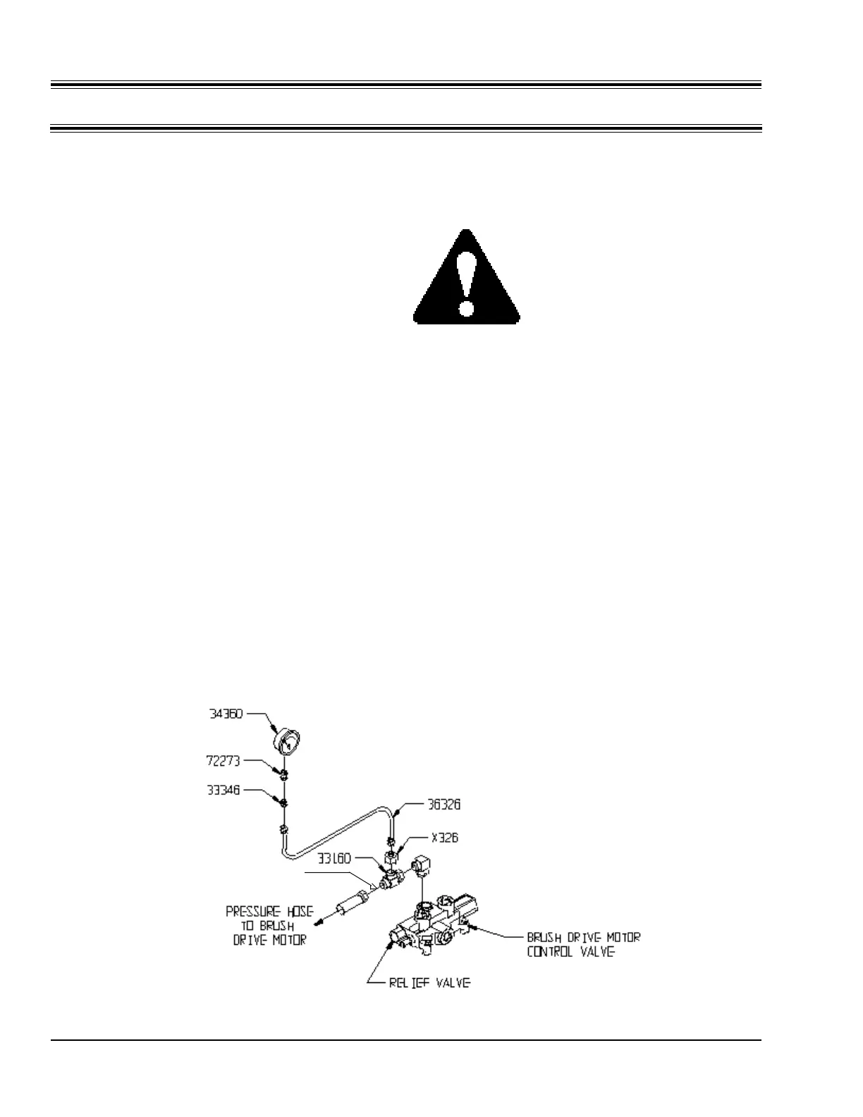
Figure 4-E
Setting Brush Rotation Relief Valve
B. Adjusting Brush Rotation Relief Valve -
The Brush Rotation Circuit gets its hydraulic flow
from the excess flow port of the hydraulic pump.
This flow has no relief valve at the pump. The
relief valve is built into the brush rotation control
valve. This valve controls the forward and
reverse rotation of the brush drive motor. The
valve is located below the operator's platform on
the right side of the broom.
Adjust the relief valve if:
- Brush stalls frequently
- Brush lacks sweeping power
- There is a constant noise while sweeping
1. Plumb a 0 to 5000 psi gauge into the Brush
Rotation Flow Circuit as shown in Figure 4-
E. Parts needed for this step, including a
pressure gauge, can be obtained from your
authorized Rosco dealer. Part numbers
are shown. Pressure port to Brush Motor
must be blocked with cap as shown.
2. Turn Brush Float control valve OFF
(clockwise until stopped).
3. Start the engine and warm up the hydraulic
oil to at least 100° F.
4. Set the parking brake and be sure the
transmission is in neutral.
CAUTION: Use extreme
caution when working under the
ROSCO Broom while adjusting
Brush Rotation hydraulic
pressure. Have another person
who is familiar with the machine
assist you.
5. Engage the Brush Rotation control handle
to turn the brush in the forward direction.
6. Increase engine speed to 2500 RPM.
7. Take a pressure reading. The pressure
gauge should read 3000 +/- 100 psi.
8. Disengage the Brush Rotation control
lever.
9. Adjust the Relief Valve by removing
locknut and turning the adjusting screw
clockwise to increase pressure and
counterclockwise to decrease pressure.
Turn adjusting screw in 1/8 turn
increments and repeat steps 5 thru 8 until
correct pressure is obtained.
INSTALL CAP, 72305