NK Series User Guide (1.0) Installation • 3–21
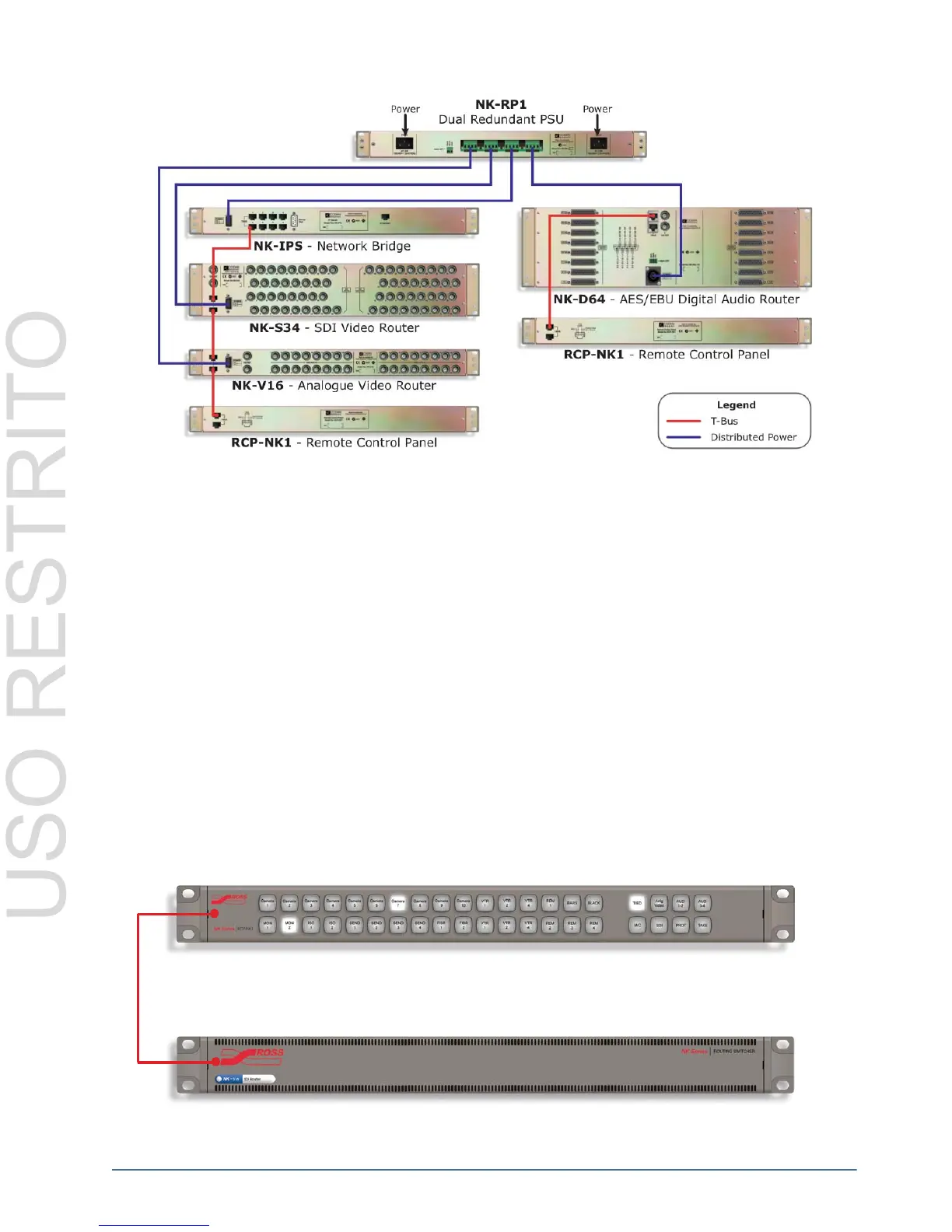
Figure 3.37 Example of NK-RP1/P Power Connections
Connecting NK Components
Unpacking and Pre-Installation
After unpacking NK components, please inspect all NK Series components for any signs of damage that may have
occurred during transportation. In the event of such damage, please notify a Ross Video representative immediately.
NK Series components should be installed in an adequately ventilated rack frame, ideally in an appropriate
environment for audio visual equipment. Relative humidity should be no more than 70% (non-condensing) and
temperatures should not exceed 30°C or 86°F.
If the above conditions are not attainable for operation, it is advised that NK Series routers be installed with 1 RU
space between them before use.
Connection Overview
NK Series components are connected via the T-Bus multi-drop control system by a single CAT5 Ethernet cable.
Routers are supplied with their own power supply, the NK1 panels are phantom powered by the routers they are
connected to via the CAT5 cable. Each control panel has two RJ-45 ports for phantom power and communications.
When connecting devices, either port may be used to connect panels or routers to each other.
Figure 3.38 Single Panel Connection Example
Address
21
13
NK Series Control Panel
NK Series Router Level
RS-485
T-Bus