NK Series User Guide (1.0) Configuration • 4–3
RCP-NKM/Q Control Panel Default Configuration
The RCP-NKM and RCP-NKQ default configuration is viewed by opening the editor for the device in the Phoenix
Control Surface.
See the RCP-NKM Remote Control Panel User Guide for more information about the RCP-NKM default
configuration.
See the RCP-NKQ Remote Control Panel User Guide for more information about the RCP-NKQ default
configuration.
Key Assignments Default
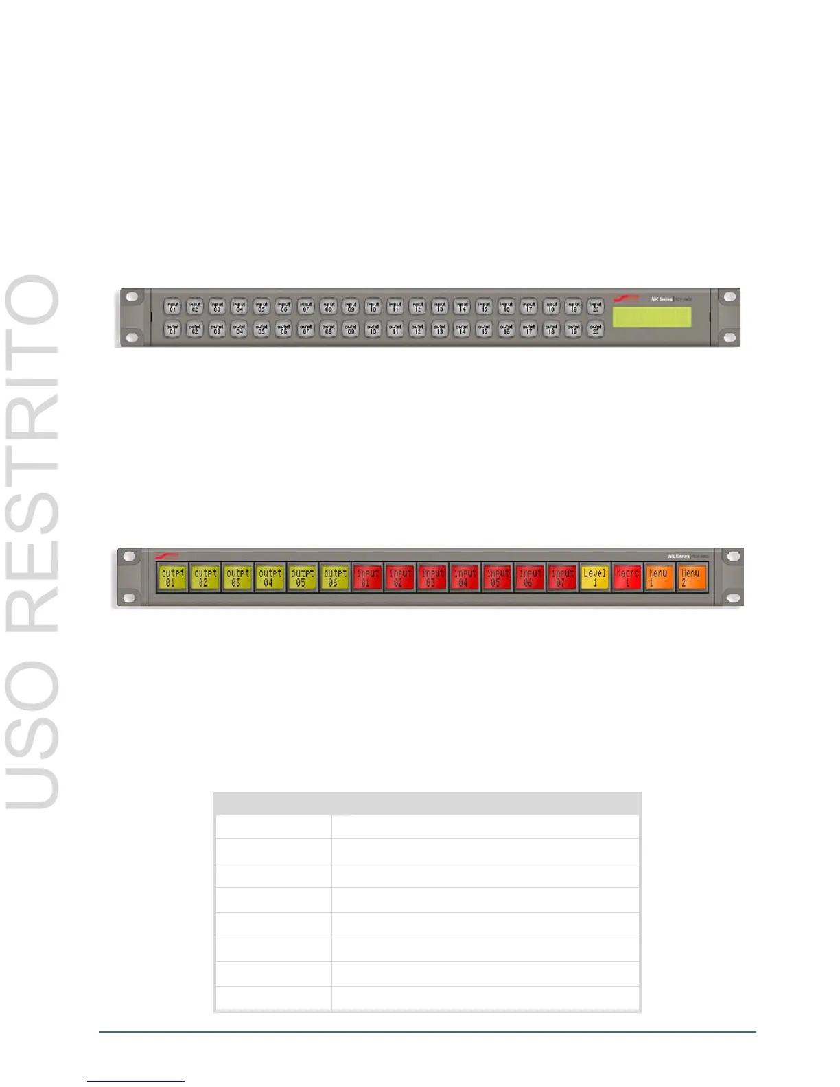
By default, the 20 keys in the top row on the RCP-NKM are assigned as sources and the 20 keys in the bottom row
are assigned as destinations.
Figure 4.2 RCP-NKM Control Panel Default Configuration
By default, the RCP-NKQ has these key assignments:
• keys 1 to 6: destinations (outputs 1 to 6 respectively)
• keys 7 to 13: sources (inputs 1 to 7 respectively)
• key 14: Level 1 (MD)
• key 15: Macro 1
• key 16: Menu 1
• key 17: Menu 2
Figure 4.3 RCP-NKQ Control Panel Default Configuration
Breakaways Default
The default breakaway is tied, that is, the first eight router levels are switched together when requested from the
RCP-NKM or RCP-NKQ.
Router Levels Default
The RCP-NKM and RCP-NKQ send switch requests to the routing switcher. Each routing switcher is assigned a
level, or number of levels if it has been partitioned.
Table 4.2 RCP-NKM/Q Default Router Levels
Router Level Name
1 Multi-definition video
2 Serial digital interface video
3 AES/EBU digital audio 1
4 AES/EBU digital audio 2
5 Analog video
6 Analog audio (left)
7 Analog audio (right)
8 Machine control