6–2 • Appendix A: Connectors and Pinouts NK Series User Guide (1.0)
Output
Figure 6.3 shows pinouts and wiring details for unbalanced output connections (left and right channels) for the
NK-A16 model.
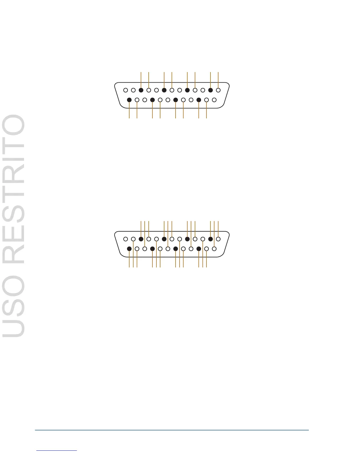
Figure 6.3 Output Pinouts
32x32 Routers
NK-A32 and NK-D32/110
Figure 6.4 shows the pinouts for both inputs and outputs 17-32 on the NK-A32 and NK-D32/110. Pinouts for
inputs and outputs 1-16 are as depicted previously.
The pinouts detailed in Figure 6.4 are applicable for both left and right channels (NK-A32 only).
Figure 6.4 Pinouts for Inputs and Outputs 17-32 on the NK-A32 and NK-D32/110
NK-A32 Model Unbalanced Wiring
Input
Figure 6.5 shows pinouts and wiring details for unbalanced input connections (left and right channels) for the
NK-A32 model.
13
1
G
-+
G
-+++
++++
GG
GGGG
--
----
2
10
4
12
6
14
8
16
1
9
3
11
5
13
7
15
13
1
G
-+
G
-+++
++++
GG
GGGG
--
----
2
10
4
12
6
14
8
16
1
9
3
11
5
13
7
15
18
26
20
28
22
30
24
32
17
25
19 21 23
27 29 31