NK Series User Guide (1.0) Appendix A: Connectors and Pinouts • 6–3
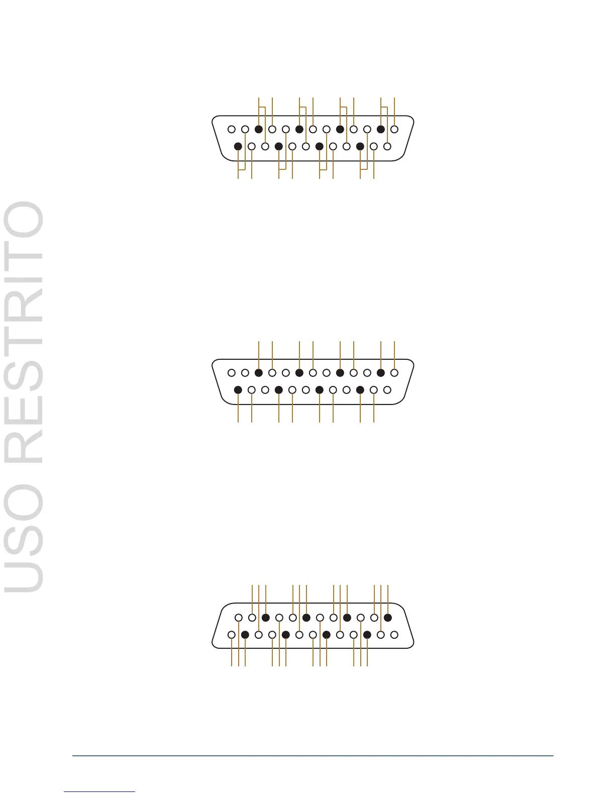
Figure 6.5 Pinouts for Unbalanced Input Connections for the NK-A32 Model
Output
Figure 6.6 shows pinouts and wiring details for unbalanced output connections (left and right channels) for the
NK-A32 model.
Figure 6.6 Pinouts for Unbalanced Output Connections for the NK-A32 Model
64x64 Routers
NK-A64
Figure 6.7 shows the pinouts for both inputs and outputs on the NK-A64. Each connector allows balanced audio of
four audio channels, please refer to Table 7.1 for relative I/O numbers.
Figure 6.7 Pinouts for Inputs and Outputs on the NK-A64
13
1
G
-+
G
-+++
++++
GG
GGGG
--
----
2
10
4
12
6
14
8
16
1
9
3
11
5
13
7
15
18
26
20
28
22
30
24
32
17
25
19 21 23
27 29 31
13
1
G
-+
G
-+++
++++
GG
GGGG
--
----
2
10
4
12
6
14
8
16
1
9
3
11
5
13
7
15
18
26
20
28
22
30
24
32
17
25
19 21 23
27 29 31
13
1
G
-+
G
-+ + +
++++
GG
GGGG
--
----
4L
8L
3L
7L
2L
6L
1L
5L
4R 3R 2R 1R
8R 7R 6R 5R