AC-825IP Panel Setup
AC-825IP Hardware Installation and User Guide 27
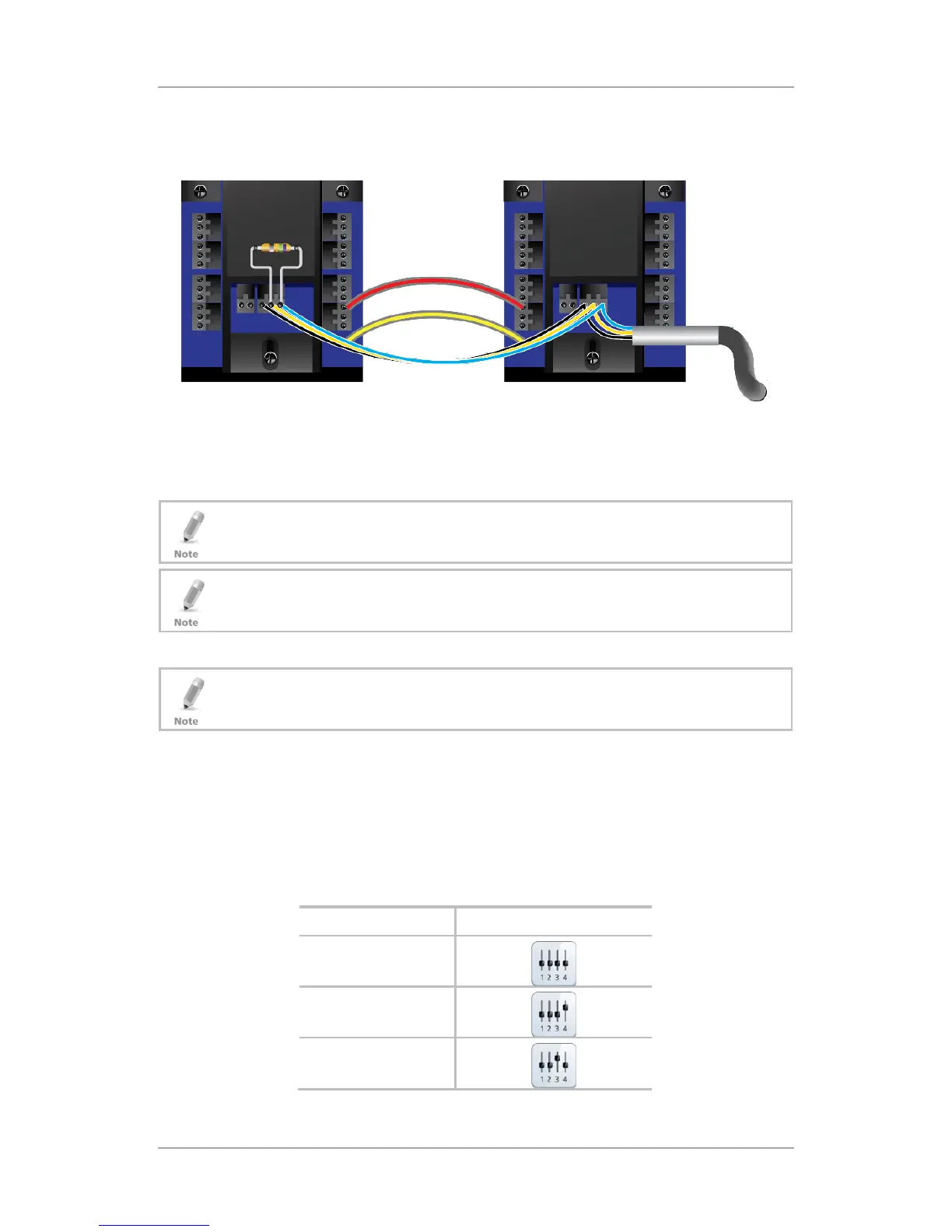
The RS-485 bus must be terminated at both ends of the cable with a
100-120 Ω resistor (Figure 20).
Figure 20: Termination with Resistor
If multi-pair twisted pair cable is used, one pair shall be used for A+ and B-
signals (blue and white/blue) and one pair for GND (orange + white/orange).
Unused wires should be terminated with 100 Ω resistors to ground at both
ends of the cable.
The maximum distance between any two ME-1515 units is 1 km. Similarly, the
maximum distance between the first ME-1515 and the last ME-1515 is 1 km.
The recommended cable type to be used is STP cat5 (shielded twisted pair
category 5). We recommend using a 20-24-AWG cable.
3.6.2 32BDIP Switching
A piggybacked expansion does not have a DIP switch address.
Each expansion board has 4 switches to determine its ID in the system. Each
switch can be set either up or down thus creating up to 16 combinations.
However, an AC-825IP panel supports up to 11 unique serial addresses
(readers) per panel, so only a maximum of 11 of the 16 serial addresses can be
used at any given time.
Table 1 shows the serial address of each of these 16 combinations.
Table 1: Serial Address and DIP Switch Combinations
Serial Address DIP Switch Setting
2
 Loading...