AC-825IP Panel Setup
AC-825IP Hardware Installation and User Guide 29
The DIP switch settings are as follows:
DIP Switches 1 to 4
These switches set the address of the reader for OSDP protocol.
DIP Switch 1 is MSB and DIP switch 4 is LSB. The address is the DIP switch state
+1.
Examples:
All the DIP switches in Off position, state is = 0 => address = 2 (in
AxTraxNG)
DIP switches 1, 3, 4 in On position and 2 in Off position, state is = 0x0B
=> address = 0x0C = 13
In every system, each board’s ID must be unique.
The ID is set only in the initialzation phase. The system does not synchronize if
an existing board’s ID is changed or if a board is added or removed. The system
must be initialized to synchronize the IDs.
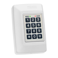
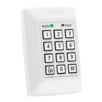
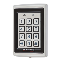
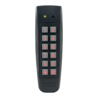
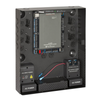
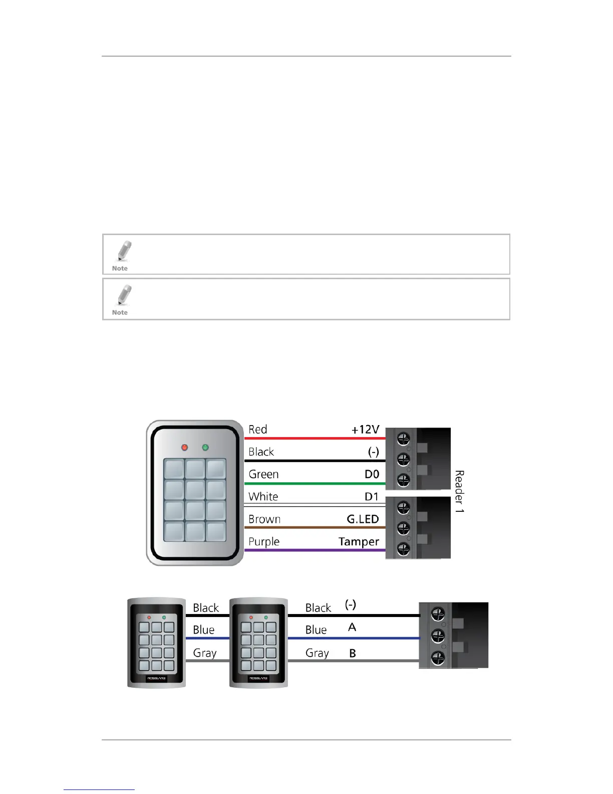
3.7 Readers and Cable Length
Readers are supplied with cables having a limited length. The color of the cable
cover represents the cable’s functionality according to the Wiegand and OSDP
standards (Figure 21 and Figure 22).
Figure 21: Reader Wiring – Wiegand
Figure 22: Reader Wiring – OSDP
 Loading...