List of Figures
AC-825IP Hardware Installation and User Guide v
List of Figures
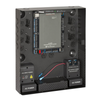
Figure 1: Sample AC-825IP Configuration..................................................... 13
Figure 2: ME-1515 Drill Holes ....................................................................... 14
Figure 3: C14 Socket .................................................................................... 15
Figure 4: Location of the Maximum Power Rating Sticker .............................. 15
Figure 5: Attaching the Pull-Safe Cable Locks ............................................... 16
Figure 6: DIN Rail ......................................................................................... 17
Figure 7: Unlocking the DIN Rail Handle........................................................ 17
Figure 8: Positioning the Panels .................................................................... 18
Figure 9: Adding a Screw as a Stopper ......................................................... 18
Figure 10: DIN Rail Dimensions (Top View) .................................................... 19
Figure 11: Input Wiring – Supervised Inputs .................................................. 20
Figure 12: Door Lock – Failed Close .............................................................. 21
Figure 13: Door Lock – Failed Open .............................................................. 22
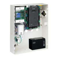
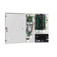
Figure 14: AC-825IP in the ME-1515 Enclosure ............................................. 23
Figure 15: AC-825IP Wiring Communications ............................................... 24
Figure 16: Slot for Expansion Board Attachment ........................................... 25
Figure 17: Daisy Chain Setup ........................................................................ 26
Figure 18: OSDP/RSDP Bus on AC-825IP Panel .............................................. 26
Figure 19: RSDP Bus on Expansion Board ...................................................... 26
Figure 20: Termination with Resistor ............................................................. 27
Figure 21: Reader Wiring – Wiegand ............................................................ 29
Figure 22: Reader Wiring – OSDP ................................................................. 29
Figure 23: Normally Open Input Connection ................................................. 31
Figure 24: Normally Closed Input Connection ............................................... 32
Figure 25: Normally Open Supervised Input (Single Resistor) .......................... 32
Figure 26: Normally Open Supervised Input (Double Resistor) ........................ 33
Figure 27: Normally Closed Supervised Input (Single Resistor) ........................ 33
Figure 28: Normally Closed Supervised Input (Double Resistor) ...................... 34
Figure 29: Connecting Multiple AC-825IP Panels to the AxTraxNG Server...... 43
 Loading...