d04924.fm
INSTALLATION MANUAL
BRP-Powertrain
Effectivity: 912 Series
Edition 2/Rev. 0
75-00-00
page 27
August 01/2012
Permissible loads (per screw)
4.4) Data for optional components of cooling system
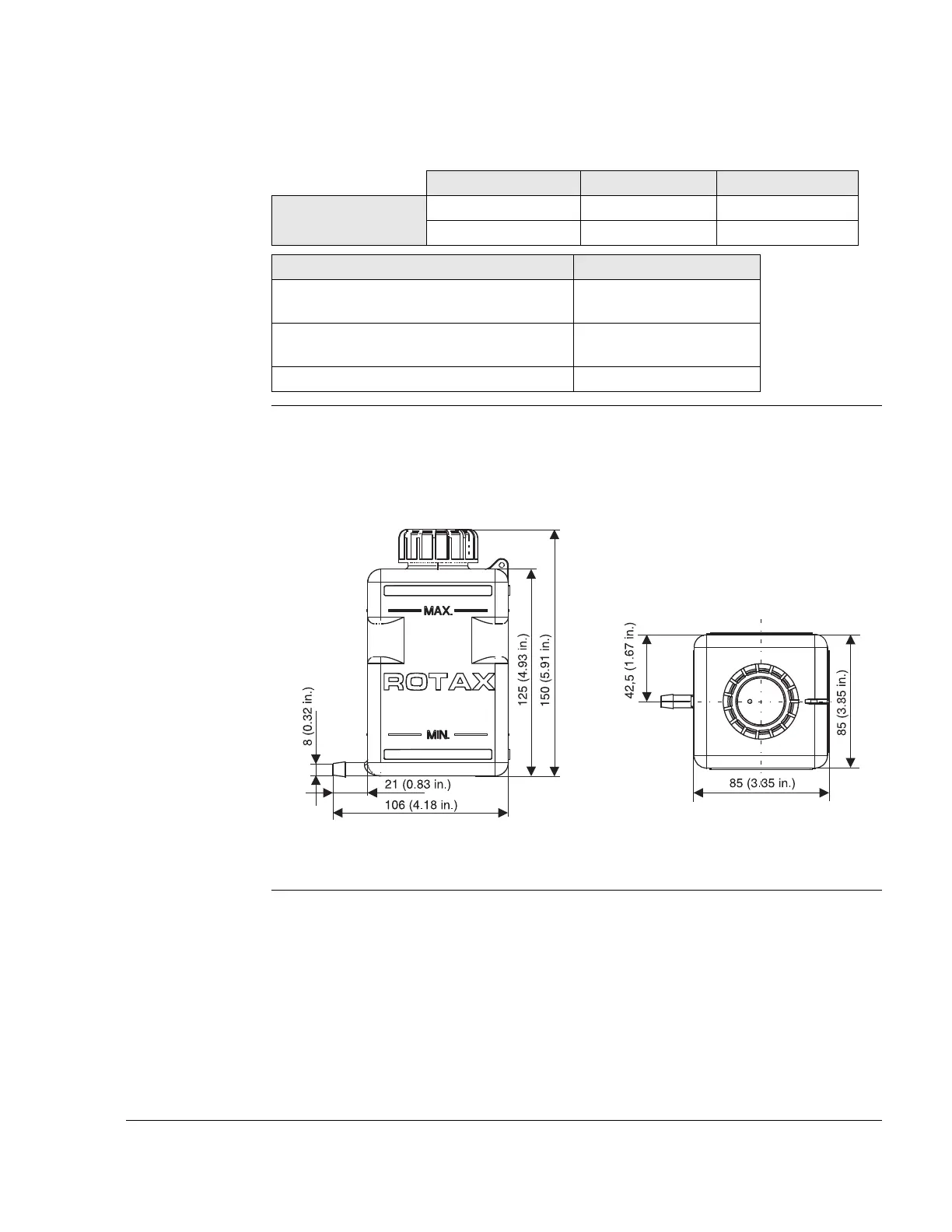
Overflow bottle See Fig. 13 and Fig. 15
Fig. 13 09148
x-axis y-axis z-axis
Attachment points -300 mm (-11.81 in.) -30 mm (-1.18 in.) -14 mm (-0.55 in.)
-300 mm (-11.81 in.) -30 mm (-1.18 in.) -14 mm (-0.55 in.)
Attachment points
Max. permissible force (safe load) in (N) on
x, y and z axis
2000 N (449.62 lb-force)
Max. permissible bending moment (safe
load) in (Nm) in x, y and z axis
50 Nm (36.89 lbft)
Min. length of thread (mm) 15 mm (0.59 in.)
 Loading...