User Manual - 21/32
XI. FITTERS MENU
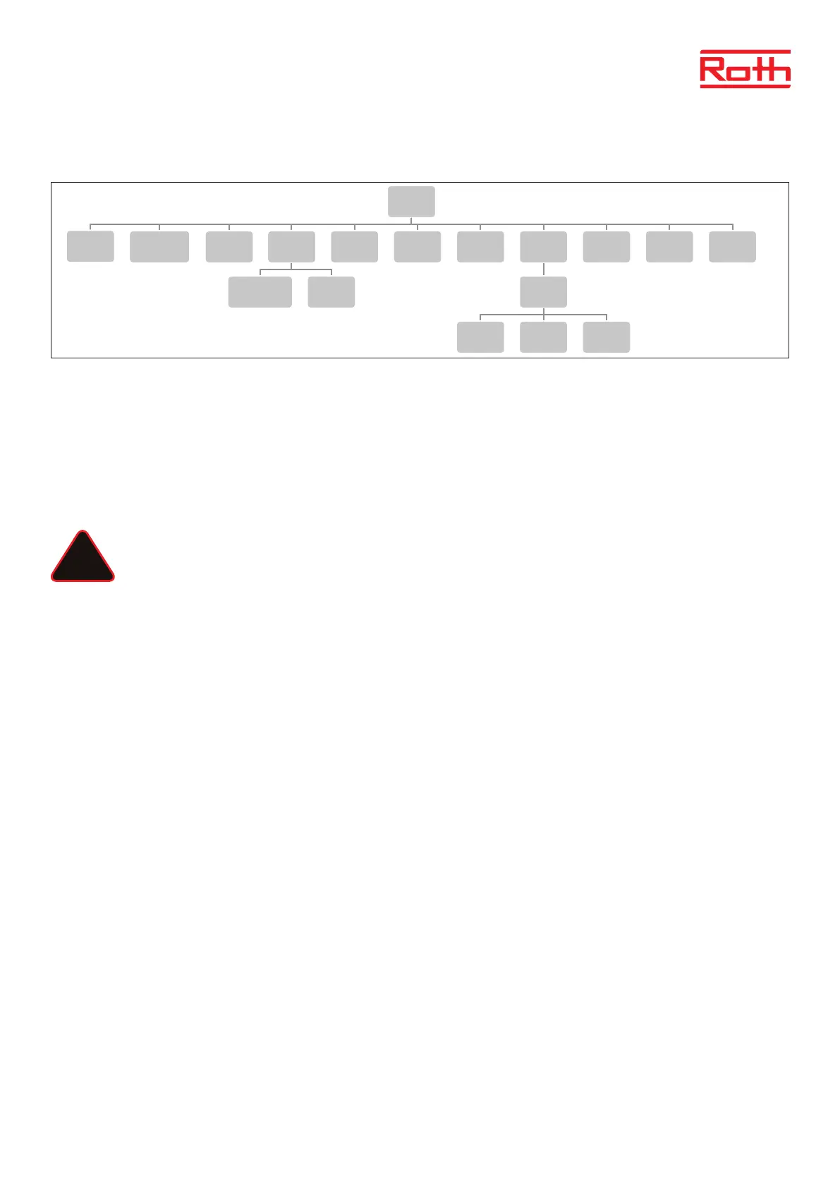
Diagram – Fitters menu
Fitter’s menu is intended to be used by a qualied person in order to congure advanced controller settings.
1. INTERNET MODULE
Roth Soline WIFI Internet module is a device enabling the user remote control of the system. The user controls the status of all system devices
on the screen of the home computer, a smart phone or a tablet and may edit certain parameters via the Internet.
The Roth Soline WiFi internet module must be connected to the master controller with the RS cable, see the specic manual for the Roth WiFi
internet module.
Aer connection of a WiFi module, all information from the WiFi module can be shown om the master controller, such as IP address, IP mask,
gateway address and DNS address from the local network.
NOTE
This type of control is available only aer purchasing and connecting the additional Roth Soline WiFi Internet module, which
is not included in the controller delivery.
2. REPEATER CONFIGURATION
An external repeater can be added to system if you have problems with the signal between the master/extension controllers or between thermo-
stats/sensors and the controllers.
In order to be able to use the Roth Soline Repeater between the master – and extension controllers, it must rst be congured. Please see the
specic manual for the Roth Soline Project repeater.
3. ADDITONAL CONTACTS
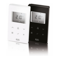
Registration Follow these steps to register the device:
> Press the registration button on EU-MW-1 (valve module)
> Select ‘Registration’ in the master controller menu
If:
> all control lights are ashing simultaneously = the registration has been successful.
> the control lights are ashing one aer another from one side to the other = EU-MW-1 module has not received the signal
from the main controller.
> all control lights light up continuously = the registration attempt failed.
NOTE
It is possible to register up to 6 EU-MW-1 devices.
Once the device has been registered, the following functions appear in the contact submenu:
Information The screen shows information about the status, operation mode, range and delay time.
ON/OFF Turns the communication with the device on/o
Delay time The contact will be enabled aer the pre-set delay time. The controller disables the contact immediately e.g. when the
pre-set temperature has been reached in every zone.
Operation mode This function enables the user to activate the operation mode in a given zone 1-8, voltage-free contact, pump or DHW.
6
Diagram – montörsmeny
Diagram – servicemeny
Diagram – meny för programvaruversion
Fitters menu
Internet
module
Repeater
configuration
Additional
contacts
Contact
operation
mode
Potential-free
contact
Pump
Radiators
zones 1 - 8
DHW Open Therm
Heating
cooling
Operation
mode
Heating Cooling Automatic
Mixing valve
Max.
humidity
Factory
settings
Service
menu
Output type Relay delay
Antifreeze
protection
Zones
Floor
heating
Hysteresis
Hysteresis
Max
temperature
Min
temperature
Factory
settings
Menu
Software
!