User Manual - 25/32
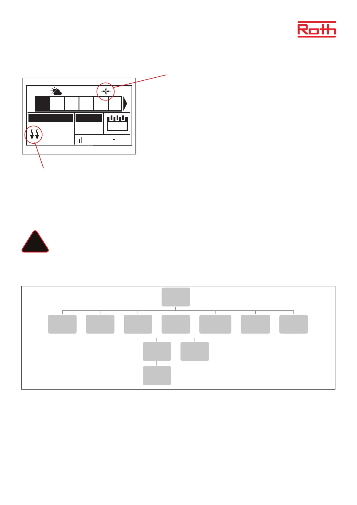
View in display during cooling operation
1. The arrows point downwards, which means that it is cooling.
2. A fan is displayed when cooling
If the maximum humidity is exceeded in a zone, the symbol 1. will switch o, but the
symbol 2. will still be on.
9. MIXING VALVE
The master controller may control additional valve with the use of a Soline Valve module. The device oers a range of parameters to adjust the
valve operation to individual needs, and also includes the possibility to run the system based on outdoor compensation.
The Roth Soline Valve module must be connected to the master controller with the RS cable. Please see the specic manual for the Soline
Valve module.
NOTE
This type of control is available only aer purchasing and connecting the additional Roth Soline Valve module, which is not
included in the controller delivery.
XII. SERVICE MENU
Diagram - Service menu
Service menu should only be used by a highly qualied person and only when it is necessary to adjust advanced settings that can have a big
inuence on the functionality and performance of the system.
Therefore the access to this MENU is also secured with a password code which is: 1234
To enter menu choose “Service menu” in the main menu – pres MENU button. Enter password by using ▼ or ▲ – press MENU to go to the next
number. Finally conrm by pressing MENU. Due to security reasons you will be automaticly thrown out of the service menu aer 1 minute.
22.3°
21.0°
13:51
CON
100% 65%
TEMPERATURE SET
Mo.
1 2 3 4 5 6
27.5°C
2
1
!
6
Diagram – montörsmeny
Diagram – servicemeny
Diagram – meny för programvaruversion
Fitters menu
Internet
module
Repeater
configuration
Additional
contacts
Contact
operation
mode
Potential-free
contact
Pump
Radiators
zones 1 - 8
DHW Open Therm
Heating
cooling
Operation
mode
Heating Cooling Automatic
Mixing valve
Max.
humidity
Factory
settings
Menu
Software
Service
menu
Output type Relay delay
Antifreeze
protection
Zones
Floor
heating
Hysteresis
Hysteresis
Max
temperature
Min
temperature
Factory
settings