A4US
US
A4
US A4
US
A4
A4 US
US
A4
US
A4
A4 US
Keeping the World Flowing
11
8) Move the actuator to the valve OPEN position using the
handwheel.
9)
Using a flat screwdriver, depress the Drive Clutch Shaft and
rotate to the “Set” position as shown on the AID faceplate.
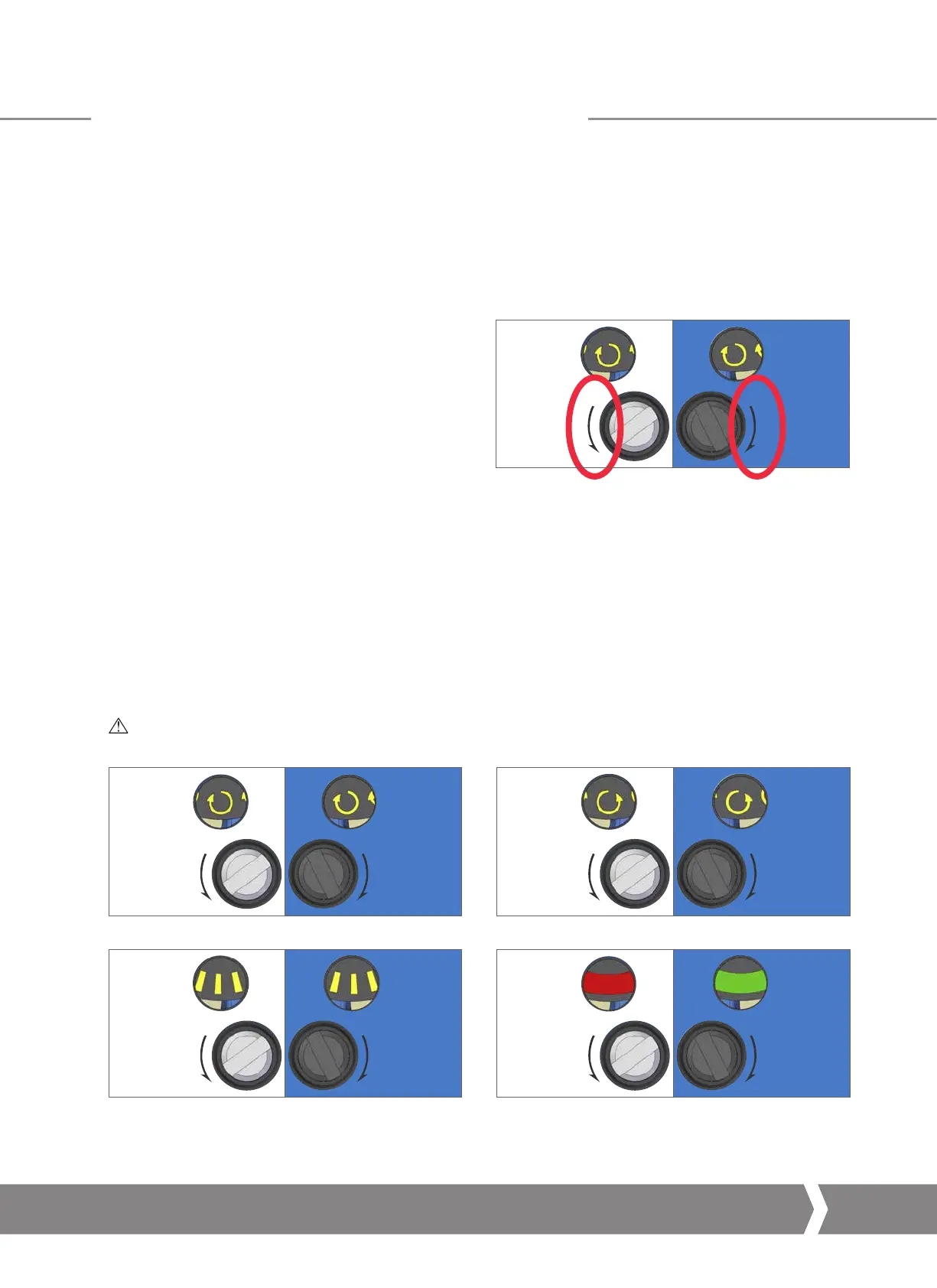
10) The OLS Adjustment Screw must now be rotated to
engage the open limit switch inside the switch mechanism.
The OLS Indicator Window will show one of four possible
symbols. Please refer to Figure 2 for direction input.
11)
Depending on where the mechanism is in the cycle, it is
possible that the switch will be approached from the wrong
direction, in this case it is necessary to move through the
limit and approach it from the correct direction. This avoids
the need to wind through the whole mechanism to reach
the limit position. The correct direction to approach the limit
is shown by the arrow next to the Adjustment Screw input.
12) Perform two checks to confirm the OPEN limit position
switch has been made correctly.
a. The feel of the Adjustment Screw will noticeably change
providing more mechanical resistance at the switching
point of the contact.
b. Use a continuity meter on the appropriate terminals –
16 & 17 for motor control and 18 & 19 for indication
feedback to check the switch is engaged.
13)
Using a flat screwdriver, depress the Drive Clutch Shaft and
rotate to the “Run” position as shown on the AID faceplate.
14) Rotate the OLS and CLS Adjustment Screws a small
amount in both directions to re-engage the mechanism
drive. A click will be heard as the drive drops back into
engagement and the adjustment screws will no longer
move in either direction.
CAUTION: This must be done or the limit will be lost
when the actuator is moved.
Rotate the OLS/CLS Adjustment Shaft Clockwise. Rotate the OLS/CLS Adjustment Shaft Anti-Clockwise.
Rotate the OLS/CLS Adjustment Shaft in the direction shown
next to the Shaft input.
The limit switching point is near or made.
Figure 2.
CK Additional Indication Drive – Basic Settings
 Loading...


