A4US
US
A4
US A4
US
A4
A4 US
US
A4
US
A4
A4 US
CK Standard and CKR Start Up Guide
10
CK Additional Indication Drive – Basic Settings
A 5mm Allen (Hex.) key and 0.8 x 4mm flat screwdriver with at
least 120mm shaft length are required to perform commissioning
of the CK Mechanical Switch Mechanism. A small torch may be
required in environments with low level lighting.
Set Torque Limits
The torque limits can be set using the same method
previously described in this manual at the beginning of the
Basic Settings section. Access to the torque setting inputs is
maintained whilst the AID module is fitted.
Set Position Limits
The position limits can still be set with the CK AID module in
place. The OLS/CLS Indicator windows and adjustment screws
can be accessed through the labelled holes in the AID chassis.
CAUTION: It is important to remove the POT drive
assembly (if fitted) from the drive gearing prior to
setting the position limits. Refer to Setting the POT
section, steps 1 and 2 for instructions on adjusting
this component.
1) Move the actuator to the valve CLOSED position using the
handwheel.
2)
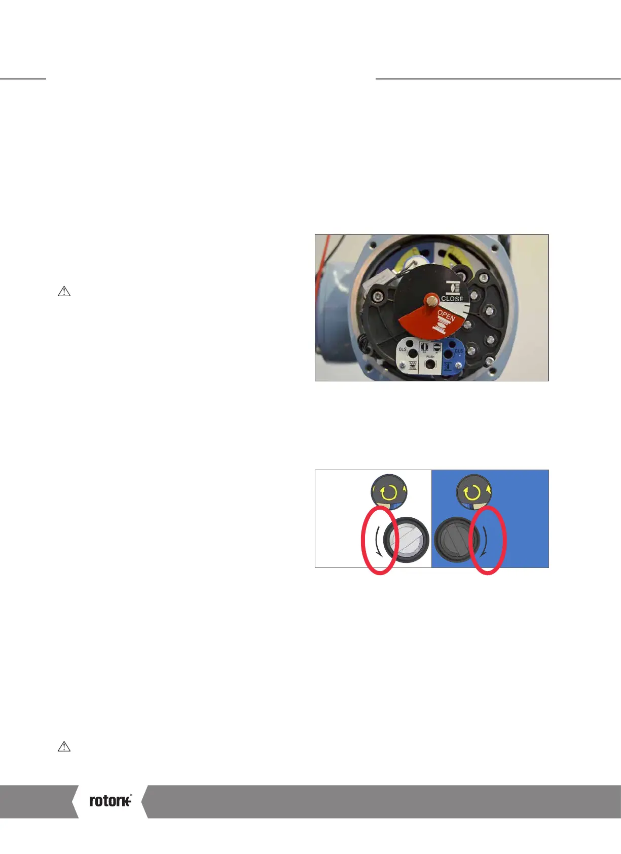
Using a flat screwdriver, depress the Drive Clutch Shaft and
rotate to the “Set” position as shown on the AID faceplate.
3) The CLS Adjustment Screw must now be rotated
to engage the closed limit switch inside the switch
mechanism. The CLS Indicator Window will show one of
four possible symbols. Please refer to Figure 2 on page 11
for direction input.
4)
Depending on where the mechanism is in the cycle, it is
possible that the switch will be approached from the wrong
direction, in this case it is necessary to move through the
limit and approach it from the correct direction. This avoids
the need to wind through the whole mechanism to reach
the limit position. The correct direction to approach the limit
is shown by the arrow next to the Adjustment Screw input.
5) Perform two checks to confirm the CLOSED limit position
switch has been made correctly.
a. The feel of the Adjustment Screw will noticeably
change providing more mechanical resistance at the
switching point of the contact.
b. Use a continuity meter on the appropriate terminals –
12 & 13 for motor control and 14 & 15 for indication
feedback to check the switch is engaged.
6)
Using a flat screwdriver, depress the Drive Clutch Shaft and
rotate to the “Run” position as shown on the AID faceplate.
7) Rotate the CLS and OLS Adjustment Screws a small
amount in both directions to re-engage the mechanism
drive. A click will be heard as the drive drops back into
engagement and the adjustment screws will no longer
move in either direction.
CAUTION: This must be done or the limit will be lost
when the actuator is moved.
 Loading...


