A4US
US
A4
US A4
US
A4
A4 US
US
A4
US
A4
A4 US
CK Standard and CKR Start Up Guide
8
CK Additional Indication Drive – Switch Testing
Test feedback switches
WARNING: Isolate the main power supply to the
actuator and remove the Plug & Socket cover.
1) Undo the four retaining cap screws on the switch
mechanism cover and remove the cover to show the
switch mechanism.
2) Confirm the torque or limit switches are functional by
measuring the relevant feedback terminals on the plug
assembly (see below).
It is not possible to test a switch that is already actuated by
the mechanism (for instance, at the end of travel limits). To
ensure that all switches can be tested correctly, move the
actuator to a mid-travel position and confirm that none of
the switches are active before beginning the test procedure.
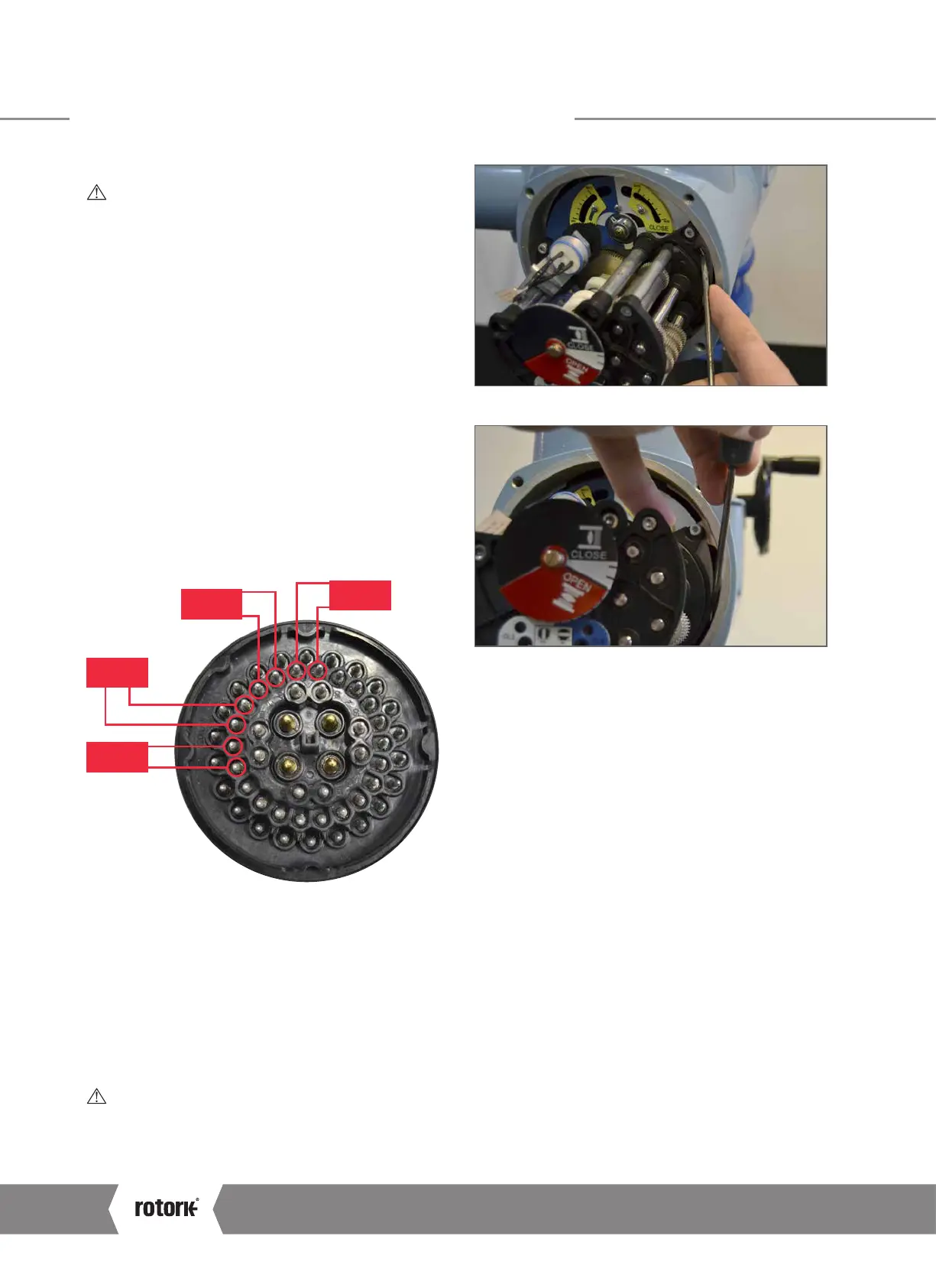
3) Test the position switches in both directions using the
LS TEST lever shown on the right hand side of the unit
between the AID module and the Mechanical Switch
Mechanism (move DOWN for open, UP for close).
4) Use a continuity meter across the following pairs of
terminals to test each individual function.
N/O OLS
N/C OLS
N/O CLS
N/C CLS
19
18
17 16
15
14
12
13
N/C CLS – Normally Closed (break when active) Close Limit
contact for motor control
N/O CLS – Normally Open (make when active) Close Limit
contact for feedback indication
N/C OLS – Normally Closed (break when active) Open Limit
contact for motor control
N/O OLS – Normally Open (make when active) Open Limit
contact for feedback indication
INFO: It is important to recognise the rotation of the
exposed plug when performing actuator function
diagnostics. The central “U” locating point provides
an orientation reference for this testing procedure.
 Loading...


