A4US
US
A4
US A4
US
A4
A4 US
US
A4
US
A4
A4 US
CK Standard and CKR Start Up Guide
14
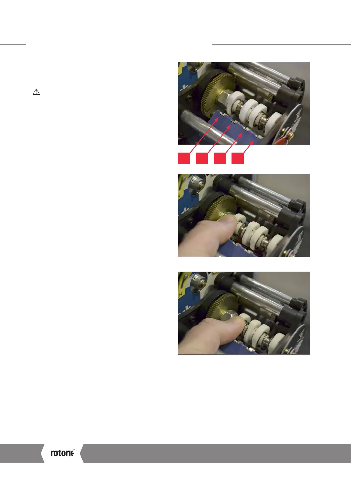
CK Additional Indication Drive – Basic Settings
Setting Intermediate Switches
The AID Module can include four additional switches to
indicate configurable intermediate positions.
CAUTION: The actuator position limits must be
configured prior to setting the Intermediate Switches.
1) Move the actuator to the desired intermediate position
using electrical operation or the handwheel.
2) Move the switch cam along the shaft against the spring
to allow free rotation of the cam.
3) Rotate the cam to ensure the desired switch behaviour
is achieved. The intermediate position switches can
be supplied with normally open or normally closed
contact form.
4) Confirm the switch has been engaged/disengaged by
measuring continuity across the relevant terminals during
cam adjustment – refer to actuator wiring diagram
and pictorial annotations (right) for the relevant switch
information.
5) Repeat steps 1 to 4 for each intermediate position switch.
IP4 IP3 IP2 IP1
 Loading...


