A4US
US
A4
US A4
US
A4
A4 US
US
A4
US
A4
A4 US
Keeping the World Flowing
15
CK Additional Indication Drive – Basic Settings
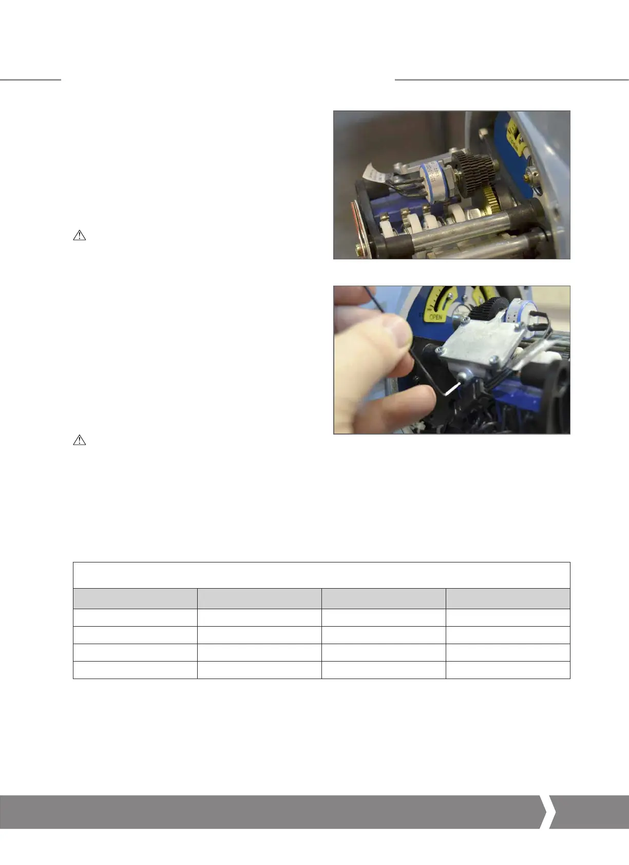
Setting the POT
The AID Module can include a potentiometer for remote
position feedback. This can provide a potentiometric output
or a 4-20 mA scaled position output via the Current Position
Transmitter option (refer to next page).
The POT drive includes four different sized gears that allow
the single turn POT to be scaled according to the total valve
travel. For information on which ratio is suitable for your
application please contact Rotork.
CAUTION: The actuator position limits must be
configured prior to setting the AID POT drive.
1) Loosen off the retaining grub screw using a 1.5mm Allen
(Hex.) Key.
2)
Rotate the POT drive assembly away from the driving gear.
3) Move the actuator to the Closed Limit position using
electrical operation or the handwheel.
4) Connect a test meter across the POT terminals* – refer
to actuator wiring diagram and POT Setting Information
table below.
5) Rotate the POT input gears until the required resistance
value has been reached.
6) Refit the POT assembly to the AID chassis and ensu
re the
teeth mate correctly with the position drive gear.
C
AUTION: Extra care must be taken to ensure the
correct POT input gear is mated with the position
drive gear.
7) Tighten the retaining grub screw to prevent movement of
the POT drive assembly.
8) Move the actuator to the Open Limit position using
electrical operation or the handwheel.
9) Confirm the POT is reading the required resistance value.
POT Setting Information
Travel Direction Value at Closed Limit Value at Open Limit Measurement Terminals
Clockwise Low High 30 & 31
Clockwise High Low 31 & 32
Anti-Clockwise Low High 31 & 32
Anti-Clockwise High Low 30 & 31
* Potentiometer terminals may not be accessible if the AID
CPT option is also fitted. In this instance it is important
to ensure the POT does not slip throughout full valve
travel. Current should change through 4-20 mA however
tuning may be required. Refer to the next page for tuning
instructions.
 Loading...


