A4US
US
A4
US A4
US
A4
A4 US
US
A4
US
A4
A4 US
CK Standard and CKR Start Up Guide
16
CK Additional Indication Drive – Basic Settings
Setting the CPT
Once the POT drive is commissioned for full valve travel, the
CPT can be calibrated to output a 4-20 mA loop powered
signal. This can be used as direct actuator position feedback
to the site control system.
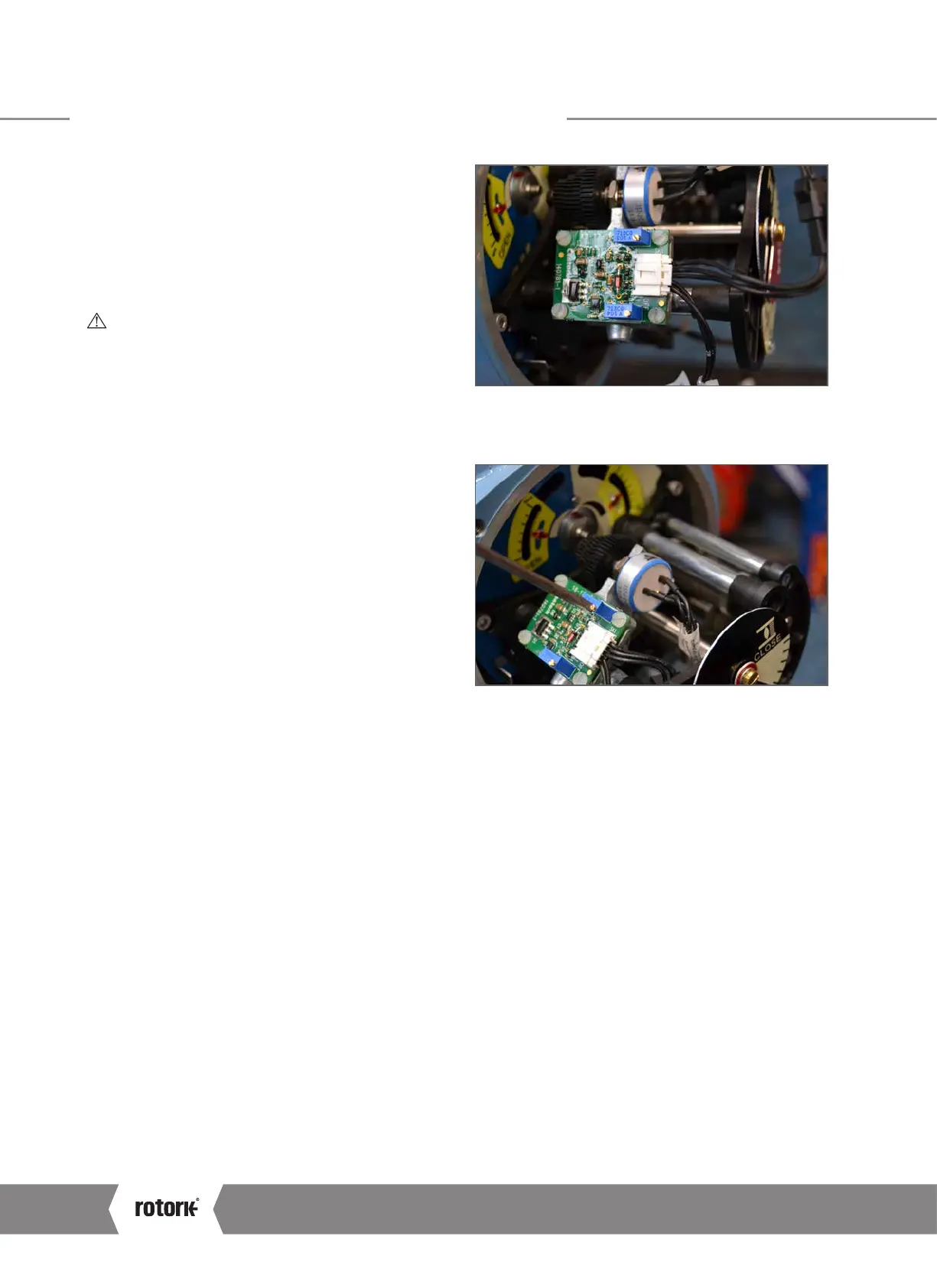
The CPT option includes two different trimming potentiometers
to enable zero and span values to be calibrated.
CAUTION: The actuator position limits and POT drive
must be configured prior to setting the AID CPT.
1) Run the actuator to the Closed position limit using
electrical operation or the handwheel.
2) Monitor position feedback using a powered test meter
across the CPT terminals – refer to actuator wiring diagram.
3) Rotate the ZERO trimming potentiometer so that 4 mA is
output from the CPT.
4) Run the actuator to the Open position limit using
electrical operation or the handwheel.
5) Monitor position feedback using a powered test meter
across the CPT terminals – refer to actuator wiring diagram.
6) Rotate the SPAN trimming potentiometer so that 20 mA is
output from the CPT.
7) Adjustment of the SPAN will cause the ZERO to change
a small amount. It is important to repeat steps 1 to 6 a
second time in order to remove this calibration error.
 Loading...


