A4US
US
A4
US A4
US
A4
A4 US
US
A4
US
A4
A4 US
Keeping the World Flowing
3
Before following any of the setting instructions included in
this document it is important to pay attention to the warnings
and safety instructions included in PUB111-007 provided with
the actuator.
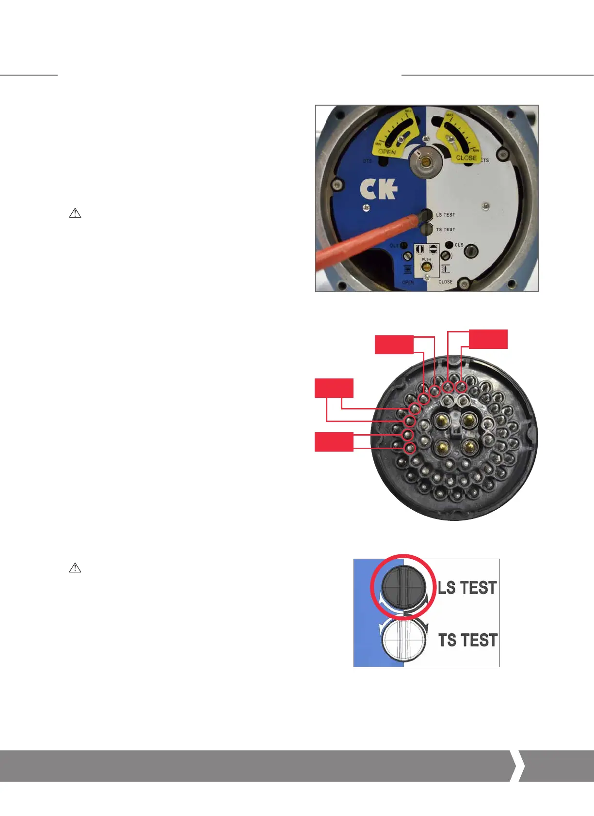
A 5mm Allen (Hex.) key and 1.0 x 5.5mm flat screwdriver are
required to perform testing of the CK Mechanical
Switch Mechanism.
Test feedback switches
WARNING: Isolate the main power supply and all
control and indication wiring before removing the
Plug & Socket cover
.
1) Undo the four retaining cap screws on the switch
mechanism cover and remove the cover to show the
switch mechanism.
2) Confirm the torque or limit switches are functional by
measuring the relevant feedback terminals on the plug
assembly (see below).
It is not possible to test a switch that is already actuated
by the mechanism (for instance, at the end of travel
limits). To ensure that all switches can be tested correctly,
move the actuator to a mid-travel position and confirm
that none of the switches are active before beginning the
test procedure.
3)
Test position switches in both directions using a flat
screwdriver to turn LS TEST (CW for open, ACW for close).
4) Link a continuity meter across the following pairs of
terminals to test each individual function.
N/C CLS
– Normally Closed (break when active) Close Limit
contact for motor control
N/O CLS
– Normally Open (make when active) Close Limit
contact for feedback indication
N/C OLS
– Normally Closed (break when active) Open Limit
contact for motor control
N/O OLS
– Normally Open (make when active) Open Limit
contact for feedback indication
INFO: It is important to recognise the rotation of the
exposed plug when performing actuator function
diagnostics. The central “U” locating point provides
an orientation reference for this testing procedure.
N/O OLS
N/C OLS
N/O CLS
N/C CLS
19
18
17 16
15
14
12
13
CK Mechanical Switch Mechanism – Switch Testing
 Loading...


