A4US
US
A4
US A4
US
A4
A4 US
US
A4
US
A4
A4 US
Keeping the World Flowing
9
CK Additional Indication Drive – Switch Testing
Test feedback switches (cont.)
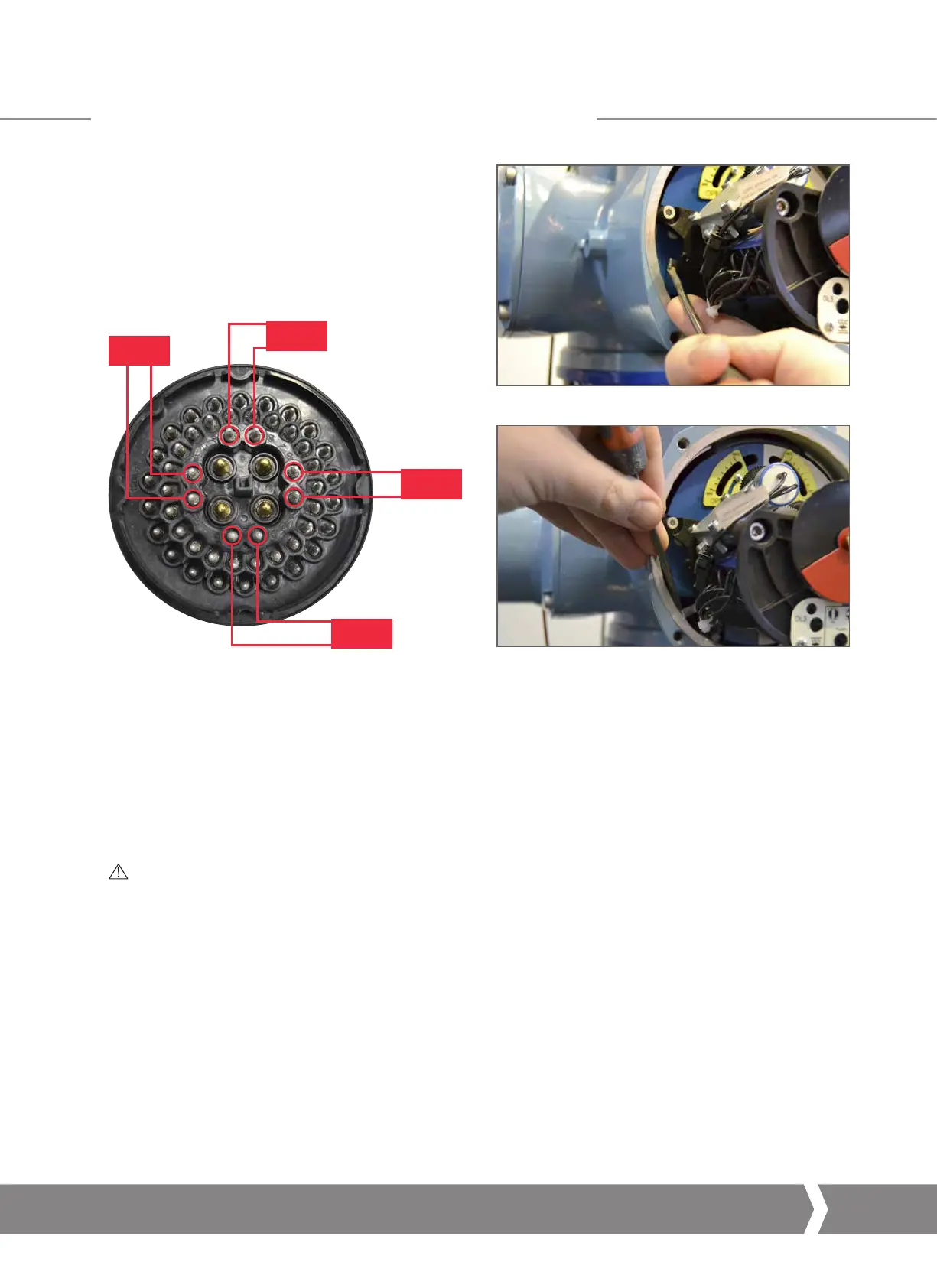
5) Test the torque switches in both directions using the
TS TEST lever shown on the left hand side of the unit
between the AID module and Mechanical Switch
Mechanism (move DOWN for open, UP for close).
6) Use a continuity meter across the following pairs of
terminals to test each individual function.
N/C CTS
5
N/C OTS
9 8
N/O CTS
6
7
N/O OTS
10
11
4
N/C CTS – Normally Closed (break when active) Close
Torque contact for motor control
N/O CTS – Normally Open (make when active) Close Torque
contact for feedback indication
N/C OTS – Normally Closed (break when active) Open
Torque contact for motor control
N/O OTS – Normally Open (make when active) Open Torque
contact for feedback indication
INFO: It is important to recognise the rotation of the
exposed plug when performing actuator function
diagnostics. The central “U” locating point provides
an orientation reference for this testing procedure.
 Loading...


