12
Installation & Maintenance Instructions
LOCAL
POS
I
T
‘UP’ ‘DOWN’ ‘MODE/CANCEL’ ENTER
POS
I
T
REMOTE
Remote Mode Selected Non-Critical Fault Alarm
‘UP’ ‘DOWN’ ‘MODE/CANCEL’ ENTER
Critical Fault Alarm
POS
I
T
LOCAL
VIEW
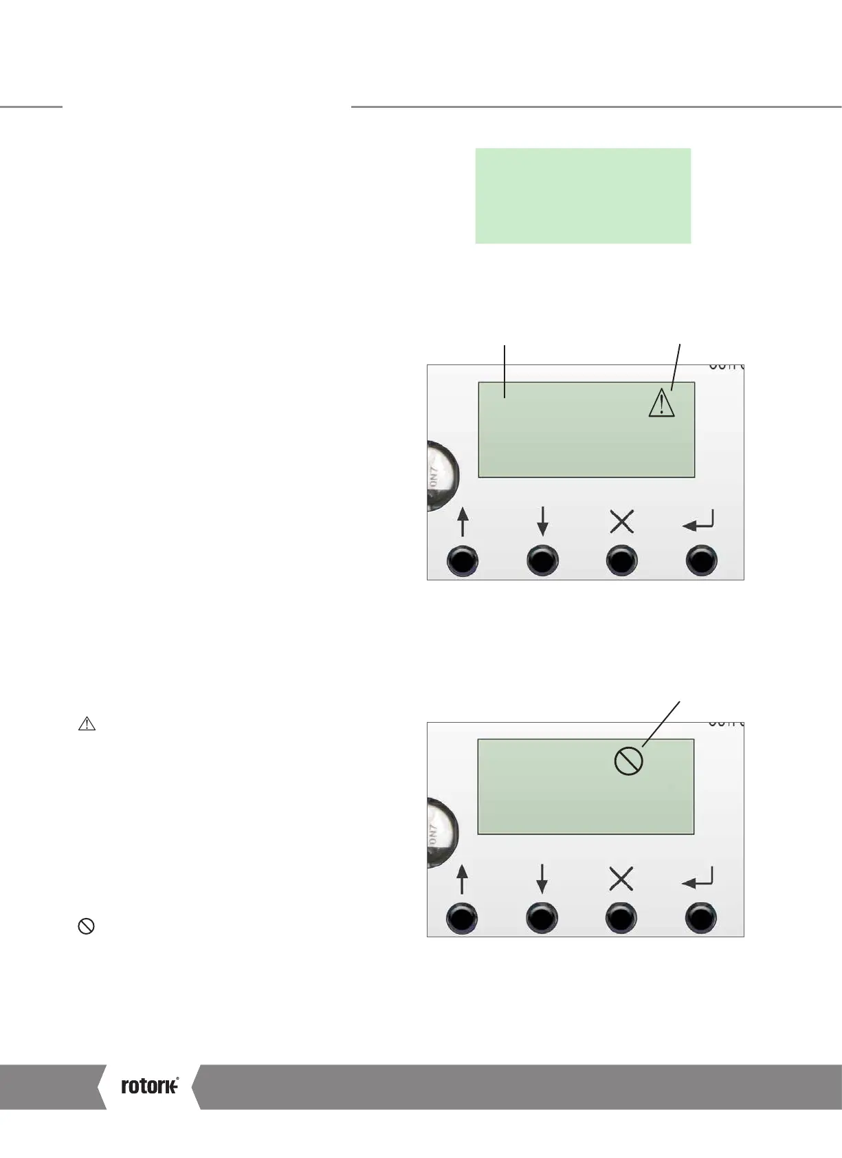
5.2.3 LCD Display
The user interface has a LCD Display that shows STATUS and
configuration information.
The default screen is the POSIT parameter.
The active operating mode, LOCAL or REMOTE, is shown in
the top left corner of the LCD.
5.2.4 Setup Pushbuttons
4 push buttons are positioned below the LCD display to
enable menu navigation and parameter configuration.
Push button functions are as follows:
‘UP’
Navigate menus in view mode. Increase parameter values in
Edit Mode.
‘DOWN’
Navigate menus in view mode. Decrease parameter values in
Edit Mode.
‘MODE/CANCEL’
Exit and return to previous menu. Cancel changes to the
active configuration parameter.
ENTER
Enter sub menu or configuration parameter. Save changes to
the active configuration parameter.
5.2.5 Fault Indication
NON-CRITICAL FAULT
An alarm condition exists which does not prohibit actuator
movement.
Non-critical faults are:
STALL
Thrust Overload
Loss of Communications
Loss of Demand Signal
Over Temperature
Power Loss
CRITICAL FAULT
An alarm exists which prohibits actuator movement.
Critical faults are:
Loss of Feedback
EEPROM Fault
Fig 5.6 LCD display
Fig 5.7 Symbol and status information
Fig 5.8 Symbol and status information
5.0 Actuator Identification
A4US
US
A4
US A4
US
A4

 Loading...
