Keeping the World Flowing
17
6.3 Electrical Installation
6.3.1 Cable Entries
The 4 cable entries are tapped either ¾” NPT or M25.
Remove any transit plugs. Make off cable entries appropriate
to the cable type and size. Ensure that threaded adaptors,
cable glands or conduit are tight and fully waterproof. Seal
unused cable entries with steel or brass threaded plugs.
If the actuator is to be installed in a hazardous area, a suitably
certified cable gland must be fitted with the use of a certified
thread adaptor where appropriate.
Unused entries must be closed with a suitably certified
blanking plug.
Wiring installation must comply with local statutory
regulations.
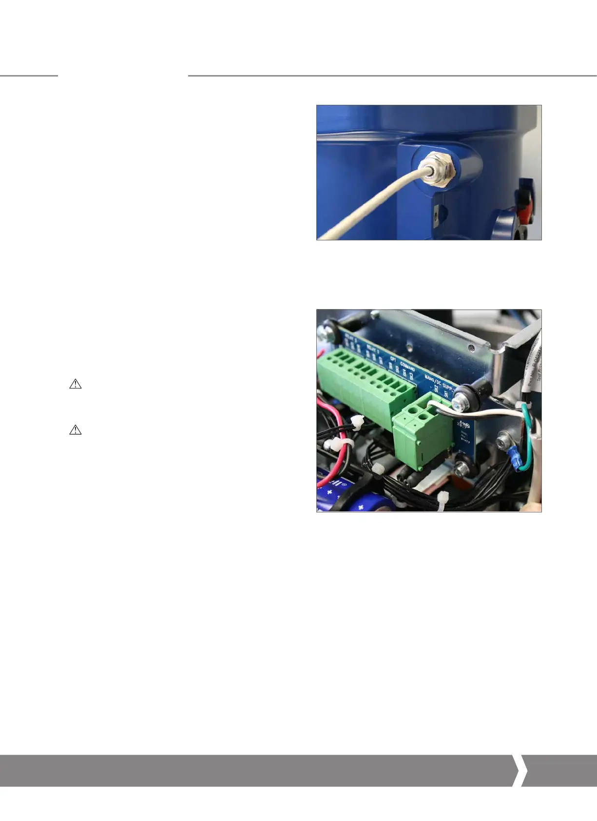
6.3.2 Connecting to Terminals
The wiring diagram supplied is particular to each actuator and
must not be interchanged with any other actuator. Check the
actuator nameplate to confirm wiring diagram number.
Refer to the wiring diagram to identify functions of terminals.
6.3.3 Cover Removal Precautions
WARNING
Carefully follow warning guidance provided in section
4.0 when removing the actuator top cover.
WARNING
Ensure all connected power supplies are isolated
before removing the actuator top cover.
Verify the supply voltage matches that stamped on the
actuator nameplate. A fused switch or circuit breaker must
be included in the wiring installation of the actuator. The
switch or circuit breaker must be installed as close as possible
to the actuator and shall be marked to indicate that it is the
disconnecting device for that particular actuator. Actuator
must be mounted such that it is not difficult to operate the
disconnecting device.
The actuator must be protected with an over current
protection device rated in accordance with PUB094-006
which details the electric motor performance data for CMA
range actuators.
Fig 6.8 Cable gland installation
Fig 6.9 Terminal block
6.0 Installation
A4 US
US
A4
US
A4
A4 US

 Loading...
