Keeping the World Flowing
11
5.0 Actuator Identification
5.2 Inside the Actuator
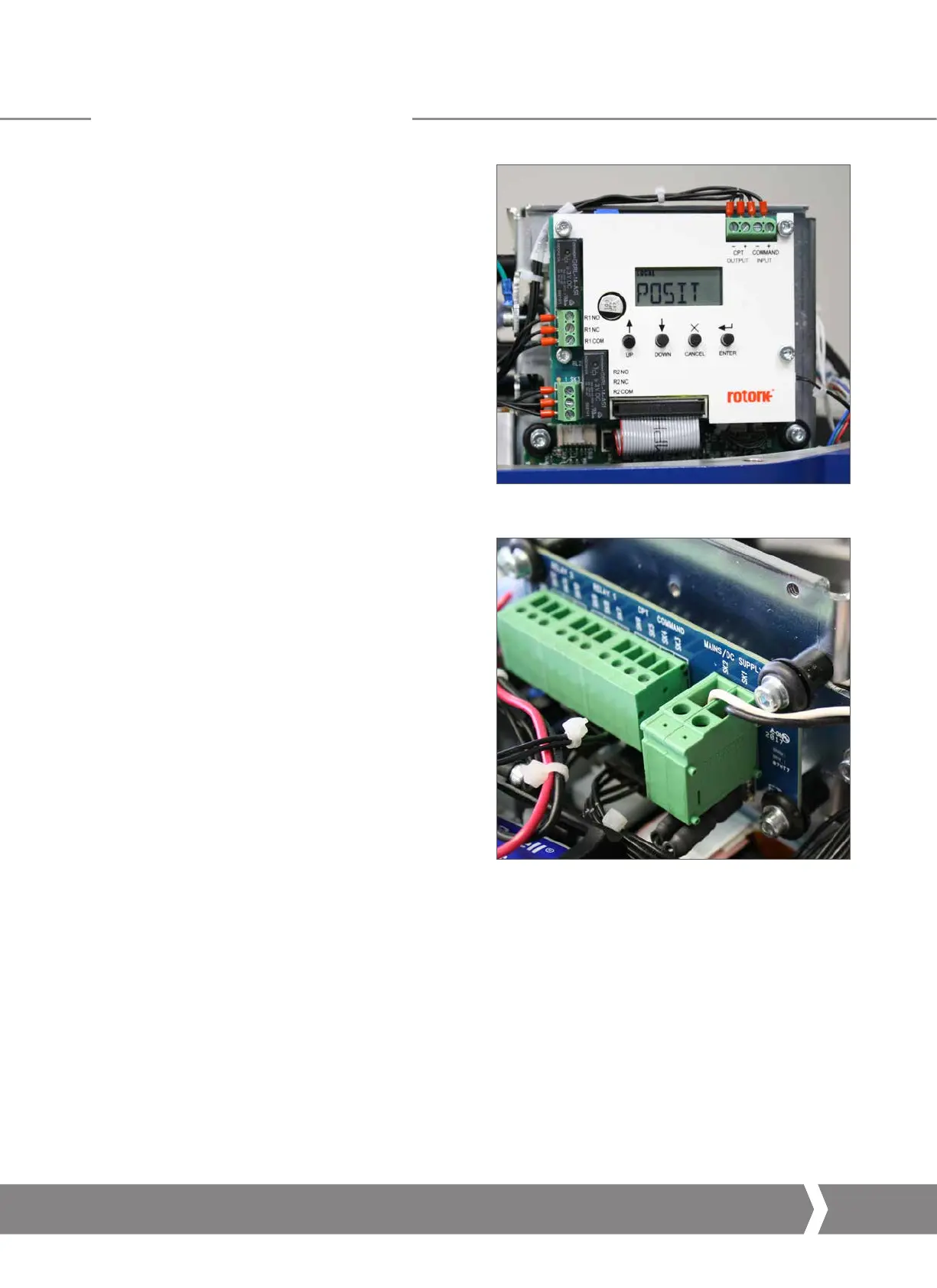
5.2.1 User Interface
Configuration of setting parameters is performed via the
internal user interface. The user interface comprises LCD
display and push buttons.
Fig 5.4 Internal interface
Fig 5.5 Terminal Block
5.2.2 Terminal Block
Connections for the power, control and indication wiring
are provided by terminal blocks fitted to the top side of the
electrical chassis. Wiring must always use appropriate crimps
and follow good wiring practices.
A4 US
US
A4
US
A4
A4 US

 Loading...
