Installation, Commissioning and Maintenance Manual
24
E. Verify the newly obtained angular position with one
stroke
F. Repeat operations A to E, until the desired angle is
obtained
G. To decrease angular stroke, rotate stop bolt (5) clockwise
5
H. Verify the newly obtained angular position with one
stroke
I. Repeat operations A to C and G to I, until the desired
angle is obtained
J. Hold stop bolt (5) with a wrench and tighten stop nut (3).
Ensure seal washer (2) is properly placed
K. Re-position seal washer (2) and verify it is correctly
positioned. Tighten cap nut (1)
2
1
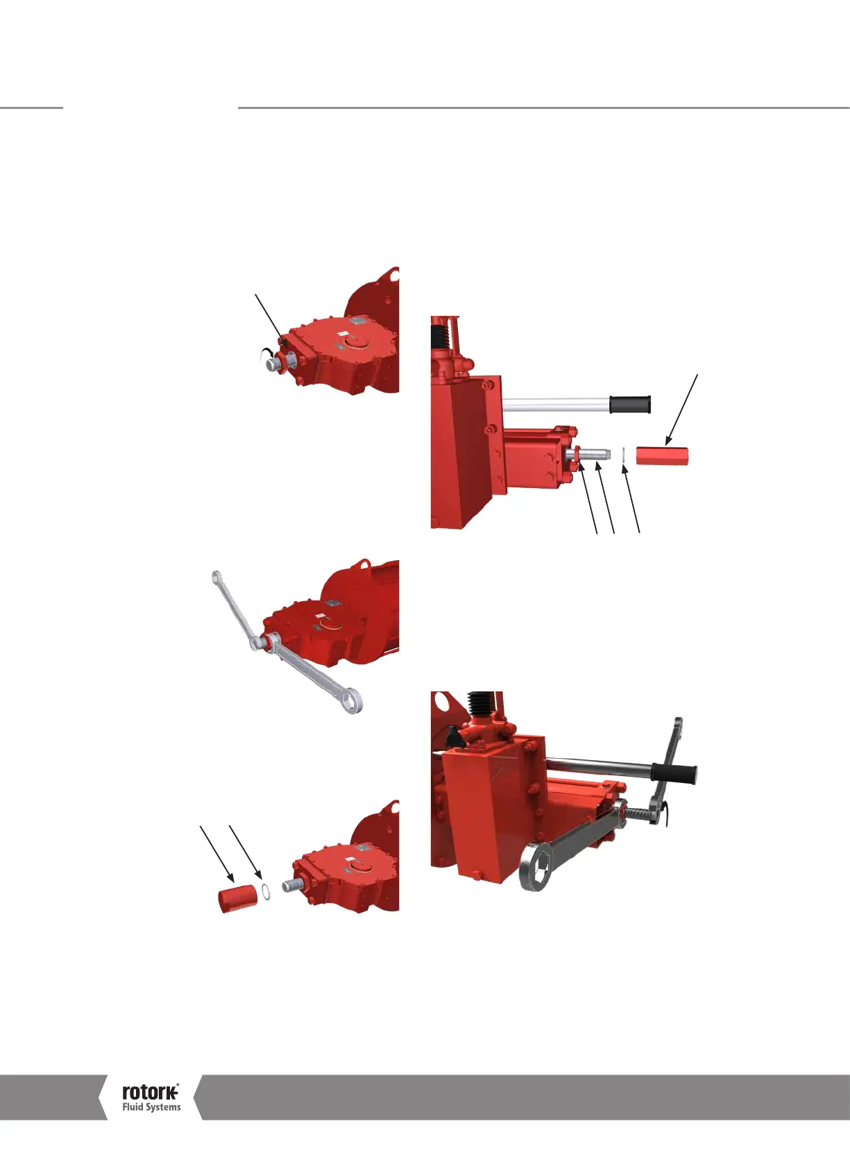
12.7.8 Double-Acting Actuator with HP1 Type Manual
Override, Cylinder Stop Bolt Setting
Perform the following operations as first setting.
Adjust the stop bolt located in the end flange of the hydraulic
cylinder, as follows:
A. Verify the absence of pressure
B. Loosen cap nut (4) with relative seal washer (5) and
loosen stop nut (6)
4
56 7
C.
Slowly pressurize the cylinder to detach stop bolt from piston
D.
To increase angular stroke, rotate stop bolt (7) anti-clockwise
E. Remove pressure
F.
Verify the newly obtained angular position with one stroke
G.
Repeat operations A to G, until the desired angle is obtained
12.0 Operation
A4US
US
A4
US A4
US
A4
 Loading...


