© Rototilt Group AB 2018-03-16
2
1
3
English
EN
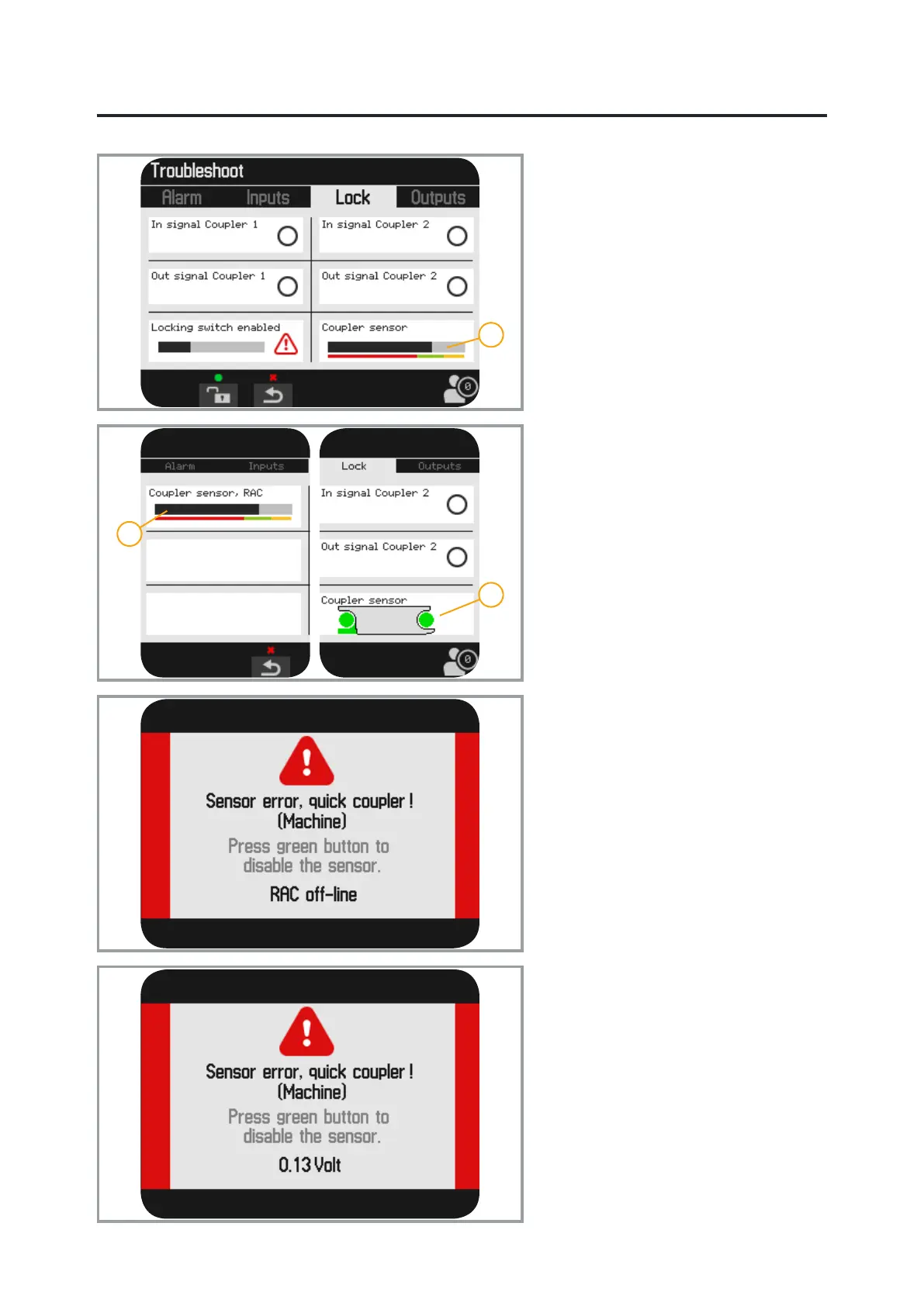
Quick coupler locking function
The menu shows information about input
and output signals to the lock circuit.
It is possible to activate the lock using the
middle function key (green).
Also refer to “Detach the tool” in the
Instructions for Use.
When the lock switch is active the two
upper circles are green.
When the valve solenoids are active the
two lower circles are green.
The location of the locking wedge is
shown with a black bar against a red-
green-yellow scale.
1. Coupler Sensor concerns the quick
coupler’s locking wedge.
2. Coupler Sensor, RAC concerns
the machine coupler/quick coupler
(excavator) locking wedge.
3. If the tiltrotator is equipped with the
option QuickChange™, the quick
coupler is shown with an alternative
icon; see Coupler Sensor.
Troubleshooting of machine
coupler
Communications error
The message RAC ofine indicates a
communications error on the CAN bus.
The warning is shown both for errors on
the CAN bus and in event of a power
failure.
Sensor failure
The message indicates a sensor error
in the machine coupler/quick coupler
(excavator).
The value of the current voltage is helpful
when troubleshooting.
Values close to 0 V indicate a short-
circuit to earth.
Values close to 5 V indicate a short-
circuit to the supply.
Detailed troubleshooting of machine
coupler/quick coupler (excavator); see
the Instructions for Use for the machine
coupler.