Chapter 3 Printing Practice
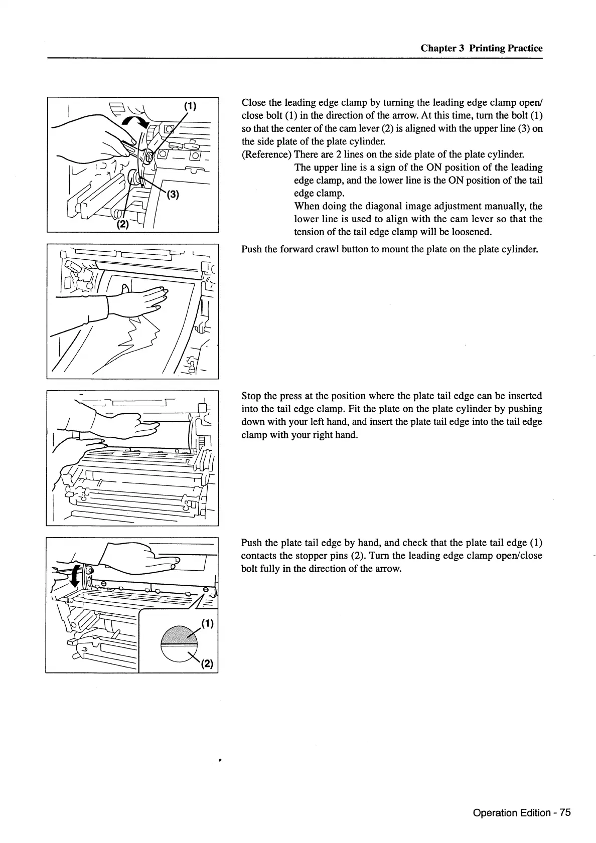
(1) Close the leading edge clamp by turning the leading edge clamp open/
I~
a(1)
(2)
close bolt (
1)
in the direction
ofthe
arrow. At this time, tum the bolt (1)
so that the center
of
the cam lever (2)
is
aligned with the upper line (3) on
the side plate
of
the plate cylinder.
(Reference) There are 2 lines on the side plate
of
the plate cylinder.
The upper line
is
a sign
of
the ON position
of
the leading
edge clamp, and the lower line
is
the ON position
of
the tail
edge clamp.
When doing the diagonal image adjustment manually, the
lower line is used to align with the cam lever so that the
tension of the tail edge clamp will be loosened.
Push the forward crawl button to mount the plate on the plate cylinder.
Stop the press at the position where the plate tail edge can be inserted
into the tail edge clamp. Fit the plate on the plate cylinder by pushing
down with your left hand, and insert the plate tail edge into the tail edge
clamp with your right hand.
Push the plate tail edge by hand, and check that the plate tail edge (1)
contacts the stopper pins (2). Tum the leading edge clamp open/close
bolt fully
in
the direction
of
the arrow.
Operation Edition - 75