(2)
Leading edge
=
Chapter 1 Operation Procedures
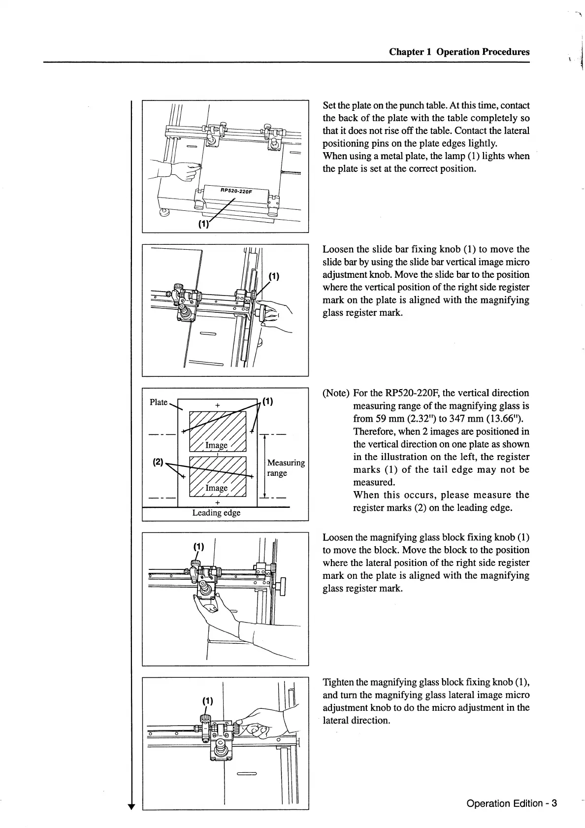
Set the plate on the punch table. At this time, contact
the back
of
the plate with the table completely so
that it does not rise off the table. Contact the lateral
positioning pins on the plate edges lightly.
When using a metal plate, the lamp (1) lights when
the plate is set at the correct position.
Loosen the slide bar fixing knob (1) to move the
slide bar by using the slide bar vertical image micro
adjustment knob. Move the slide bar to the position
where the vertical position
of
the right side register
mark on the plate is aligned with the magnifying
glass register mark.
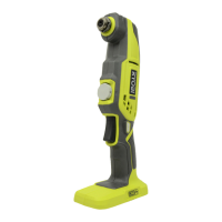
(Note) For the RP520-220F, the vertical direction
measuring range
of
the magnifying glass is
from 59 mm (2.32") to 347
mm
(13.66").
Therefore, when 2 images are positioned
in
the vertical direction
on
one plate as shown
in the illustration
on
the left,
the
register
marks
(1)
of
the
tail
edge
may
not
be
measured.
When
this
occurs,
please
measure
the
register marks (2) on the leading edge.
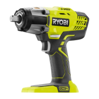
Loosen the magnifying glass block fixing knob (1)
to move the block. Move the block to the position
where the lateral position
of
the right side register
mark on the plate is aligned with the magnifying
glass register mark.
Tighten the magnifying glass block fixing knob (1),
and turn the magnifying glass lateral image micro
adjustment knob to do the micro adjustment in the
lateral direction.
Operation Edition - 3