3rd Ed. Sep 30, 06 2-3
S–TEC
2.1 Power-Up Test
Perform the actions shown in Table 2-1. For each action, verify the corresponding
response where applicable.
Table 2-1. Power-Up Test
ACTION RESPONSE
1. Set Yaw Damper Master Switch
to OFF position (if installed).
------
2. Set Trim Master Switch to OFF
position (if installed).
------
3. Set Battery Master Switch to ON
position.
------
4. Set Avionics Master Switch to ON
position.
------
5. Set Autopilot Master Switch to one
of the following positions, whichever
is applicable:
All annunciations appear on AP
display as shown in Fig. 2-1 for 10
seconds, and then extinguish.
FD/AP (Flight Director Installed)
AP (No Flight Director)
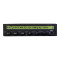
For Programmer/Computers with
serial number greater than 3001,
software revision number briefly
appears on AP display between 10
and 20 seconds following power-up,
as shown in Fig. 2-2.
RDY annunciation alone re-appears
on AP display within 3 minutes, as
shown in Fig. 2-3 (Notes 1, 2).
Notes:
1. Should a Programmer/Computer failure be detected, the FAIL annunciation
alone will re-appear on the AP display as shown in Fig. 2-4, and the autopilot will
not operate.
2. Should a Turn Coordinator failure be detected, the AP display will remain
blank indefinitely as shown in Fig. 2-5, and the autopilot will not operate.