2. Installation
41
2.2 Setting Up the Instrument
Set the control temperature for each part of the instrument, auto operation
and current time.
Perform these settings on the control panel display of the Embedding Module.
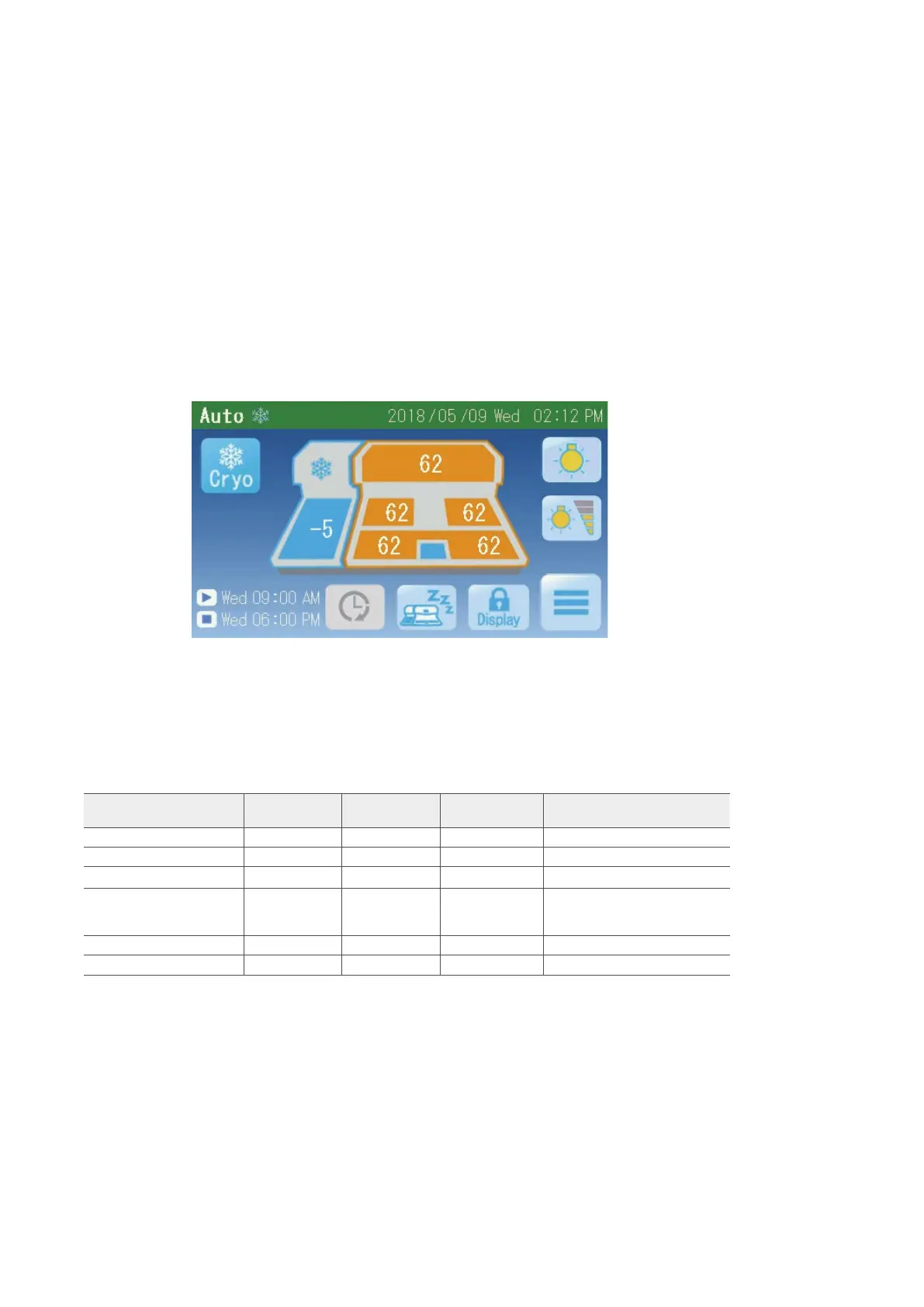
2.2.1 Temperature Setting for Each Part of the Instrument
The heating and cooling parts of the instrument are temperature-controlled at
their respective set values. Refer to Setting the Temperature in this
paragraph for information on how to change the set temperatures.
NOTE:
Shown above is an example of the Auto screen.
The factory temperature settings of the instrument are as follows:
Temperature setting
location
Setting range Temperature
display range
Factory setting of
the instrument
Remarks
[1] Parafn chamber 50 to 75°C -99 to 99°C 62°C
[2] Left warming chamber 50 to 75°C -99 to 99°C 62°C
[3] Right warming chamber 50 to 75°C -99 to 99ºC 62°C
[4] Hot plate 50 to 75°C -99 to 99°C 62°C
A temperature is displayed
separately for the left and right, but
the set temperatures are the same.
[5] Cooling plate -10 to 0°C -99 to 99°C -5°C or 0°C Only J0 is 0°C
[6] Cold spot Cannot be set. Not displayed.
NOTES:
• The forceps holder temperature is set to 8°C above the set
temperature of the hot plate. Note, however, the upper limit is
80°C
• At a room temperature of 25°C, no wind and under no load
(nothing on the cold spot), the cold spot temperature should be
between 0 and 15°C when each temperature is set to 62°C.
[1]
[2]
[5]
[4]
[3]
[6]