EB 8389-1S EN 55
Leakage sensor
Phase 2: A 0.30 % band is placed around
the last set point that the valve moved to.
One third of this band lies in front of the set
point that the valve moved to and two thirds
of the band lies behind it. The band itself is
subdivided into eleven xed points. Each
xed point is located at a distance of 0.03%
to the next point. The valve moves to the new
xed points one after the other. After reach-
ing a xed point and after the 'Settling time
before sound level measurement' has
elapsed, the leakage sensor measures the
sound pressure level.
The manufacturer reference test is successful
when the difference between the rst and last
newly dened points is larger or equal to the
adjusted 'Sensitivity sound level'.
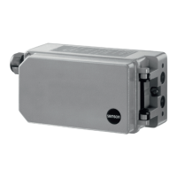
Phase 2 successful: The 'Sensitivity sound level'
(10 dB) is reached between the rst and last
newly dened points. The manufacturer test is
successfully completed.
If the 'Sensitivity sound level' is not reached
after the valve has moved to all eleven newly
dened points, then the change in sound
pressure level is too low. In this case, phase
3 starts.
Phase 2 not successful: The difference in sound
pressure level between the rst and last newly
dened points is lower than 'Sensitivity sound
level' (10 dB). Phase 3 starts.
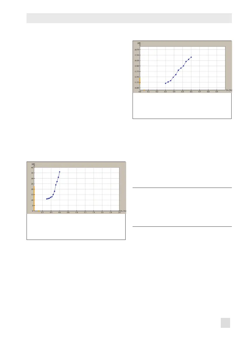
Phase 3: The valve moves to the set points
valid for phase 1 one after the other. This is
plotted in a sound level vs. travel graph. The
graph shows where the point of activation is
and to which value the 'Sensitivity sound lev-
el' must be reduced to allow the test to be
completed successfully.
Dening parameters
Note:
The parameters can only be dened in
TROVIS-VIEW4 after the 'Positioner
accessories identication' has been set
to 'Leakage sensor'.
1. Switch to manual mode.
2. Dene the parameters for the manufac-
turer reference test. Refer to Note con-
cerning editing set points.
3. Start manufacturer reference test.
The start of the reference test is docu-
mented in the Time stamp.
'D8' and 'TEST' are indicated in alternat-
ing sequence on the positioner display.

 Loading...