88 EB 8389-1S EN
SIL operator test
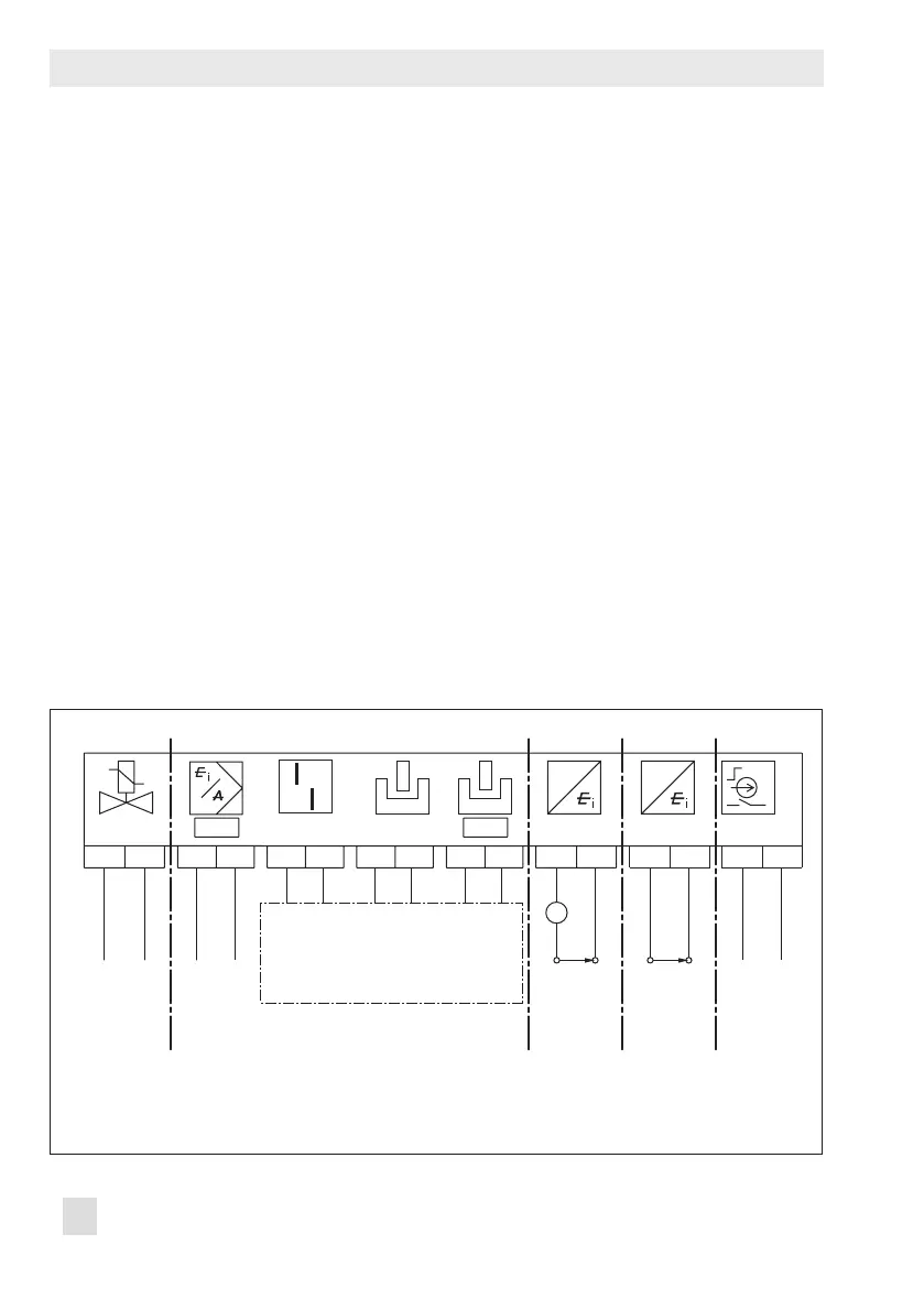
Fig. 21: Electrical connections
Switching amplier according to
EN 60947-5-6
24 V DC
Forced
venting/
solenoid valve
(optional)
mA
control
signal
A3 F
ault
alarm
output
A2
Softwar
e
A1
Software
optionally
induct
ive
Limit switches
Two-wire
transmitter
Supply unit
only for
optional
tr
ansmitter
Leakage
sensor
Binary input
Optional Optional Optional Optional
G
+81 -82 +11 -12
+83
-84 +51
-52
A2A3 A1
+41 -42
+31 -32
A
+31 -32
G
+31 -32
G
+81 -82 +11 -12
+83
-84 +51
-52
A2A3 A1
+41 -42
+31 -32
A
+31 -32
G
+31 -32
14 SIL operator test
The SIL operator ensures that the safety func-
tion of the positioner is working. The safety
function is based on the shutdown of the i/p
converter (6, Fig. 22). This causes the pneu-
matic actuator to be vented and the valve to
move to its fail-safe position.
Monitoring of the input signal
The i/p converter is switched off when the
input signal of the positioner at terminals
+11/
–12 falls below 3.8mA or 4.4mA depend-
ing on the positioner version (a signal range
of 4 to 20mA is required). See Fig. 21.
Monitoring the voltage supply
(version with forced venting and solenoid
valve)
The i/p converter and the solenoid valve
(when installed) are shut down whenever the
voltage at terminals +81/–82 falls below
12V (an input voltage of 24V DC is re-
quired). See Fig. 21.
The SIL operator test checks the emergency
shutdown by the integrated safety function
(SIL). It can be started in the manual or auto-
matic mode of control valves.
The positioner generates a permanent mes-
sage in the event that an error occurs during
the operator test. All control properties of the
positioner remain kept. Only the emergency
shutdown function of the positioner is no lon-
ger guaranteed.

 Loading...


