9-4
EB|LTR|43_EN
May 2023 edition
Subject to technical changes
Servicing
Ö Secure the actuator (500) with a crane, see the correspond-
ing actuator documentation.
Ö Mark the installation position of the actuator.
Ö Release only the screws (65) and wedge-lock-washers (67)
between the bracket (17) and the butterfl y valve.
Ö Lift the actuator with the crane and put it down in a safe
place.
Ö Disassemble the coupling (18) and secure the key(s) (68) in it
to prevent it from falling out.
Ö Remove the key(s) (64).
Ö Remove the nuts (56) and wedge-lock-washers (55) or spring
washers (59). When reassembling the spring washer set, ob-
serve the correct sequence and alignment.
Ö Release the screws (108) until the stuffi ng box can be pulled
off.
Ö Disassemble the gland (8) and remove the packing ring (39)
carefully with a suitable tool. (The support ring (239) remains
in the body.)
Ö Remove any residues in the packing area and clean it.
Ö Apply a thin layer of approved lubricant in the packing area,
see Chapter “15.1.2 Lubricants”
Damage to the butterfl y valve due to unsuitable lubricants!
The functionality of the butterfl y valve is ensured only by using a
certain lubricant. Unsuitable lubricants can corrode and damage
the surface.
Ö Only use lubricants recommended by SAMSON LEUSCH, see
Chapter “15.1.2 Lubricants”.
Ö In the case of increased requirements on the outer tightness
(TA-Luft), see Chapter “15.1.1 Tightening torques” or
LW-10007.
Ö Insert the new packing rings (39) one after the other. If avail-
able, it must be ensured that the trimmed edges are offset
with respect to each other.
Ö Assemble the gland (8), nuts (56) and wedge-lock-washers
(55) or spring washers (59).
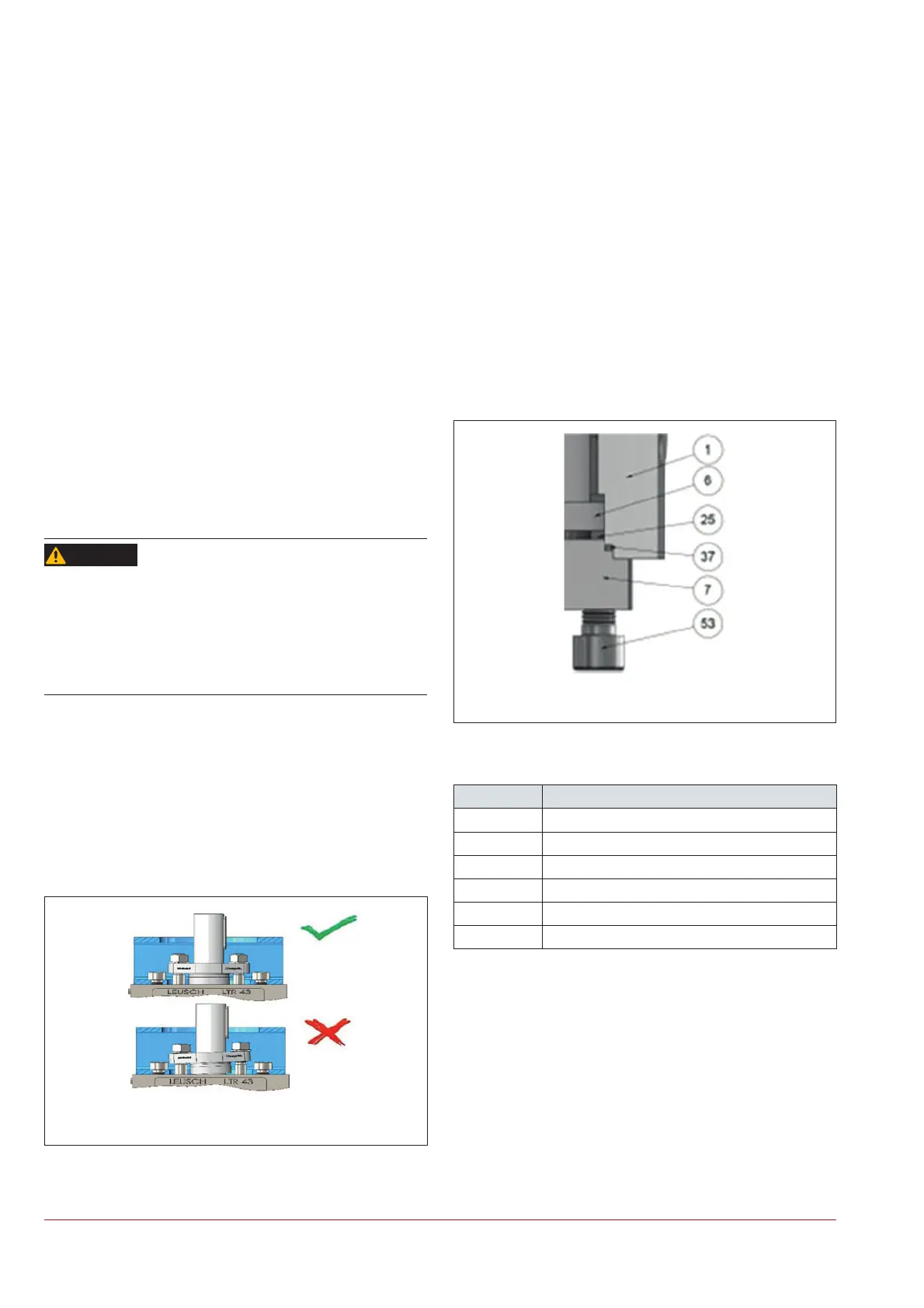
Figure|9-2: Correct tightening of the gland (8)
WARNING
Ö Tighten the nuts (56) alternately with slight manual force.
Make sure that the stuffi ng box does not tilt with respect to
the shaft.
Ö Assemble the key(s) (68).
Ö Tighten the nuts (56) in a criss-cross pattern with the specifi ed
torques, see Chapter 15.1.1 or
LW-10006 (STD) or
LW-10007 (TA-Luft).
Ö Assemble the actuator in the marked installation position.
Ö Check the tightness of the packing (39) and the functionality
of the actuator, see chapter “5.4 Checking the assembled ac-
tuator”. If the packing leaks, tighten the nuts (56) in a criss-
cross pattern in small steps. If there is still leakage, contact
SAMSON LEUSCH through the nearest SAMSON offi ce.
9.3.3.2 Replacing the gasket cover
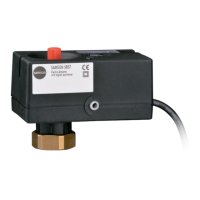
Figure|9-3: Gasket cover replacement
Table|9-2: Parts list
Pos. Designation
1 Body
6 Shaft
7 Bonnet
25 Thrust ring
37 End cap seal
53 Screw
Ö Release and remove the screws (53), see Figure 9 3.
Ö Disassemble the bonnet (7) and remove the old cover sealing
(37). During disassembly, make sure that the thrust ring (25)
does not fall out.
Ö Remove the residues and check for damage.
Ö Apply a thin layer of approved lubricant on the new gasket
cover (37) and thrust ring (25) and position them on the bon-
net (7) and install.